People always launch fireworks to celebrate festivals or large events all over the world. Dazzling fireworks bring us splendid visual sense. But at the same time, they bring some accidents when they are improper used. To reduce potential danger of skin burn and accidental explosions, we can use remote control system to ignite fireworks. That will be a better method to enjoy launching fireworks in festivals.


We will try to demonstrate our new series firework ignited system one by one with short articles and short videos.
- 1 channel firework ignitor system to ignite electric firework.
- 1 channel firework ignitor system to ignite electric igniter.
- 2 channels firework ignitor system to ignite electric fireworks.
- 2 channels firework ignitor system to ignite electric igniters.
The first demonstration is the 1 channel firework ignitor system launch electric firework.
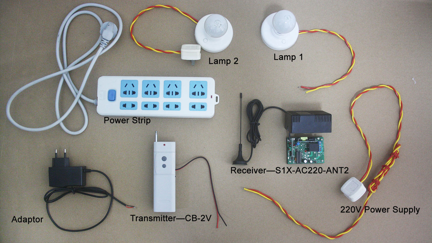
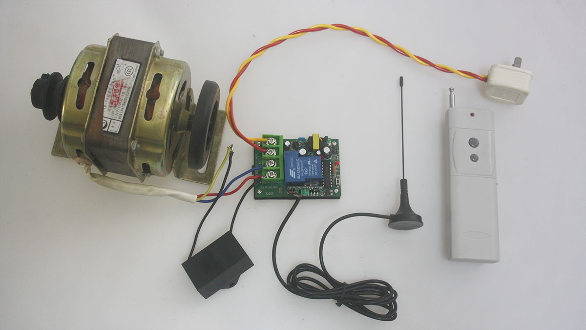
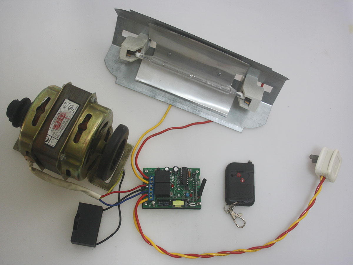
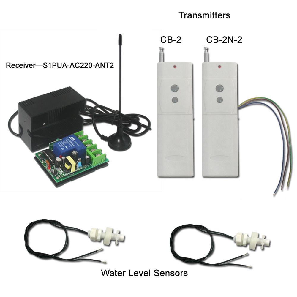
Material preparation:
1× receiver box of firework ignitor system
1×transmitter
1×electric firework
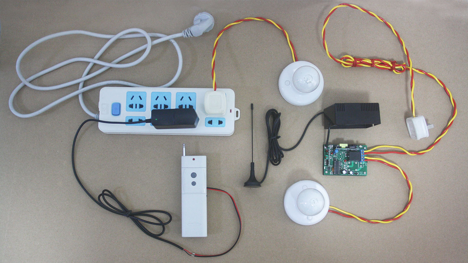
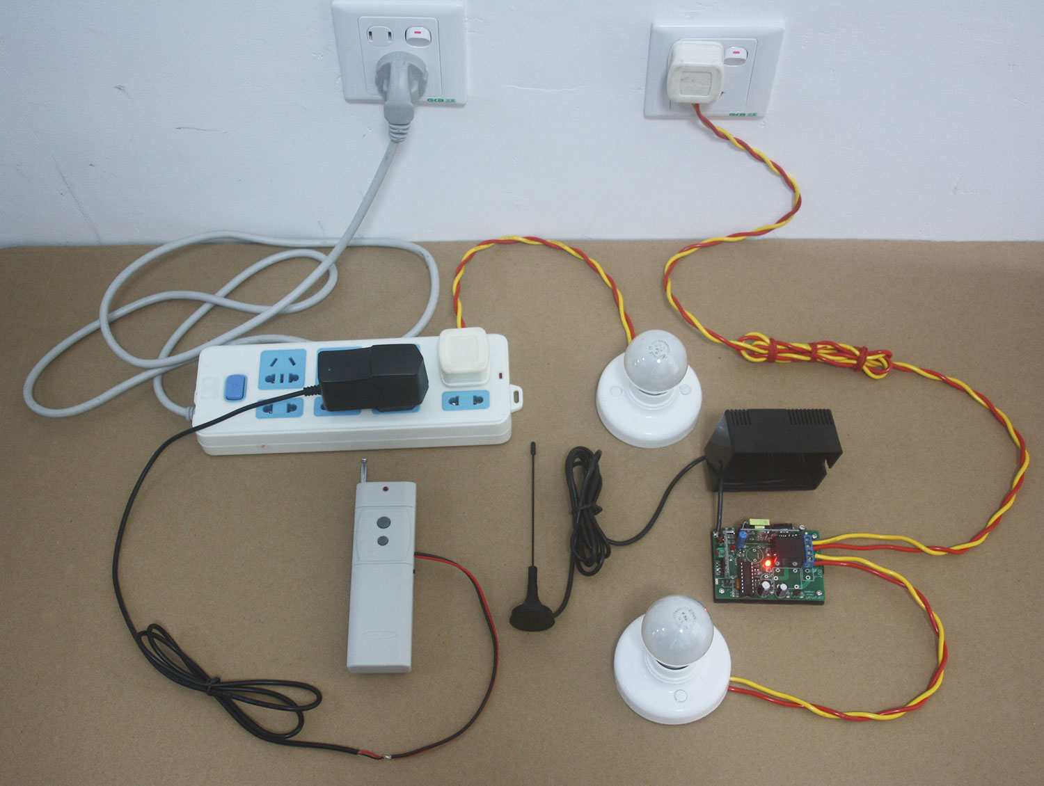
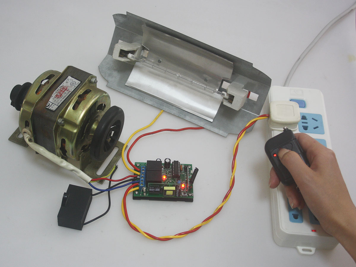
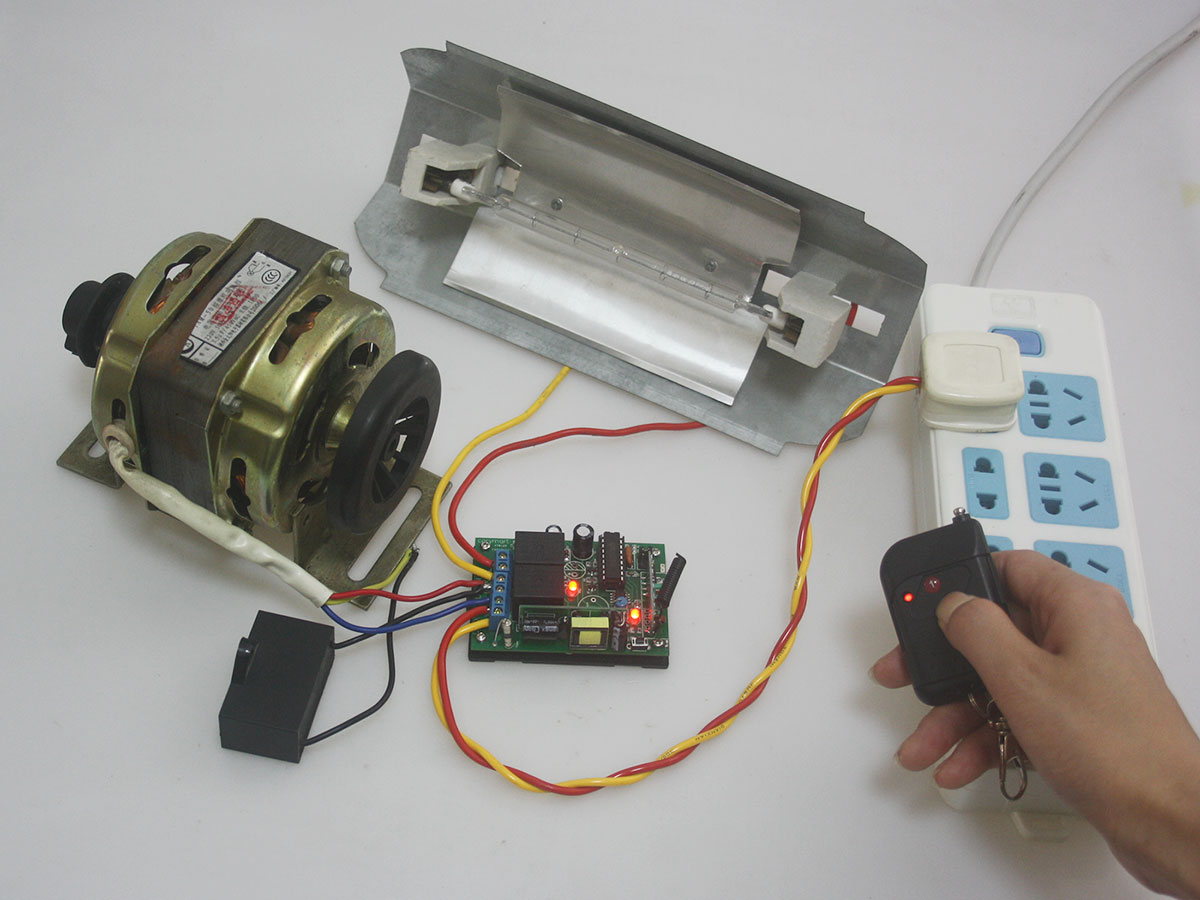
Connection and Operation:
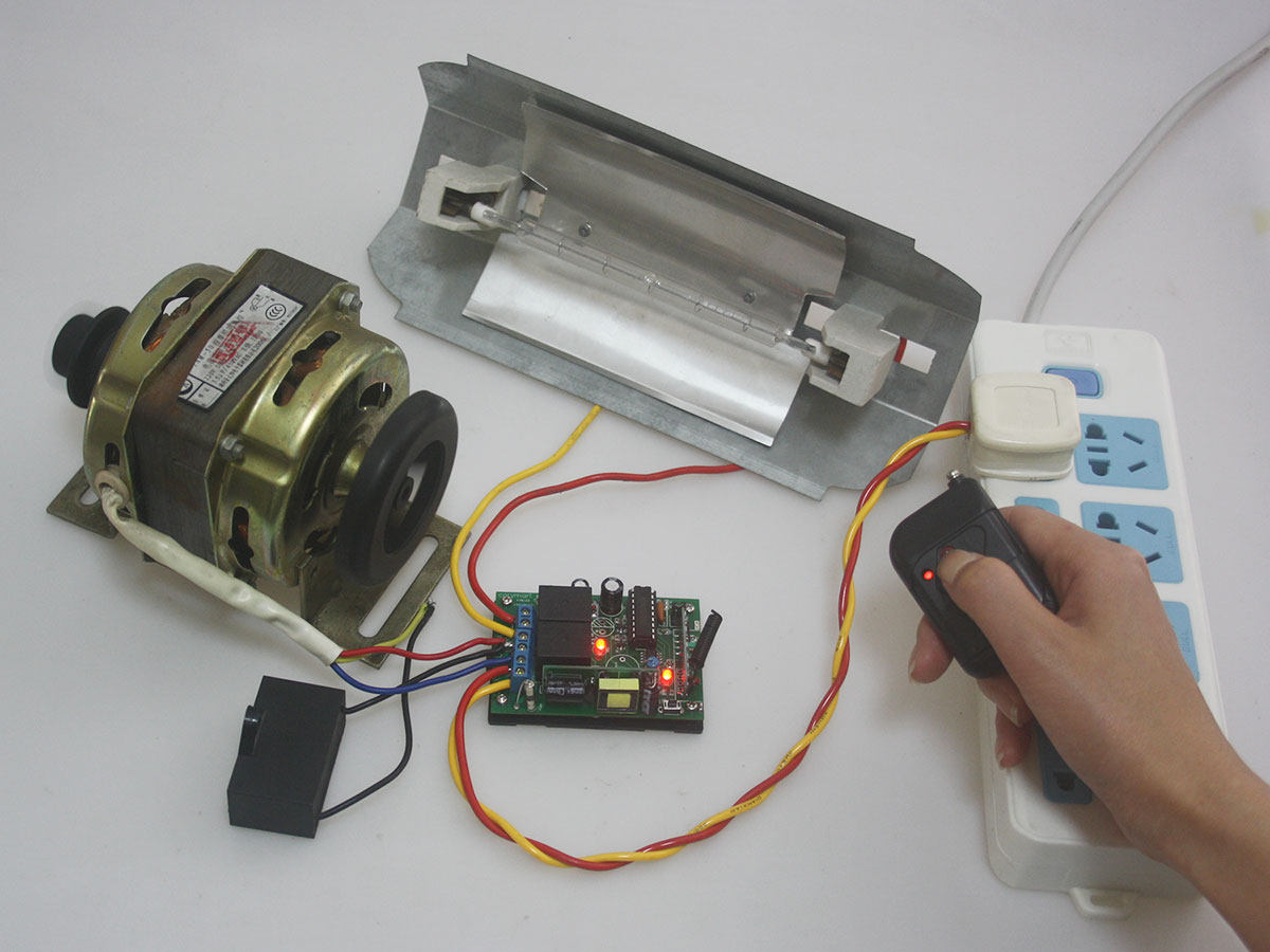
Connect two wires of electric firework to red and black terminals of the receiver.
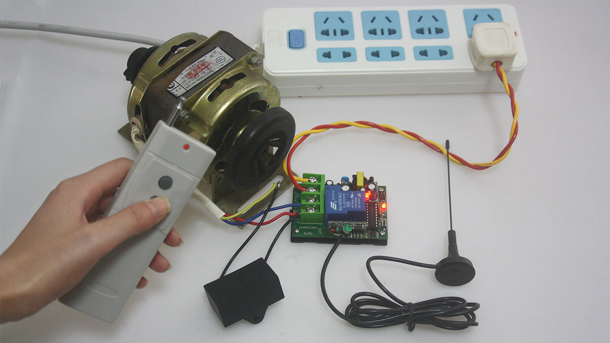
Switch on the receiver after connections.

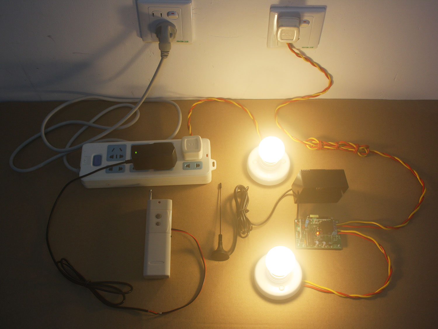
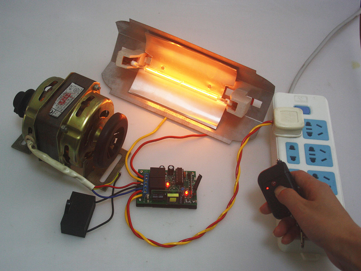
Press button, ignite firework.
Short Video for 1 channel firework ignitor system to ignite electric firework.
http://www.youtube.com/watch?v=OtoS-b6G9aI&feature=youtu.be
Online shop: www.carymart.com
Caution:
Any inflammable and explosives material must be far away when igniting fireworks.
Anyone is far away from the firework more than 50m when it is ignited.
 Follow