AC Lamp is Controlled by Non-adjustable Delay Time RF Remote Controller

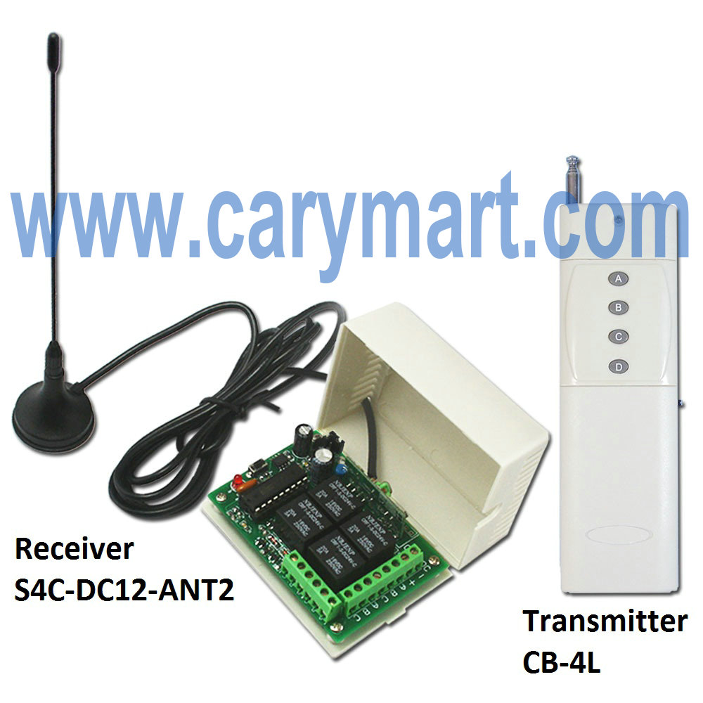
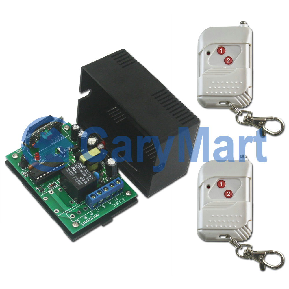
We recommend 1 channel 110V~220V customized delay time controller (S1RD-AC220+C-2). At first, it must be set delay time in advance. According to your own actual requirement, you can set delay time you want. e. g. delay time: 20 seconds. You cannot change delay time once it is set. It is applied for controlling lights, motors, fans, electrically operated door/ lock/windows/ blinds/ cars or other appliances with AC 110~240V or DC 0~28V. You can turn on/off device on the receiver with transmitter from any place within reliable distance (theoretical distance 100m), the wireless RF signal can pass through wall, floors, doors and other obstacles.
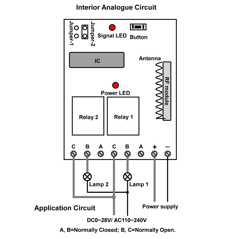
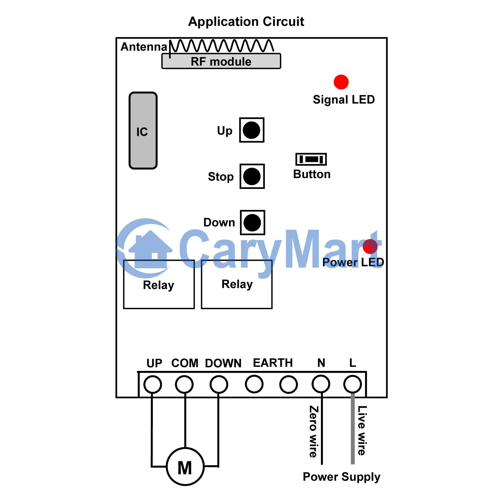
time delay remote controller

Wiring:

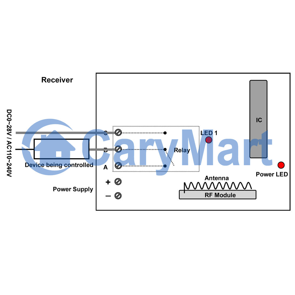
Initial state: B, C = Normally Open; A, B = Normally Closed.

AC lamp is wired to normally open terminals B&C. And add additional ac power to AC lamp.

circuit

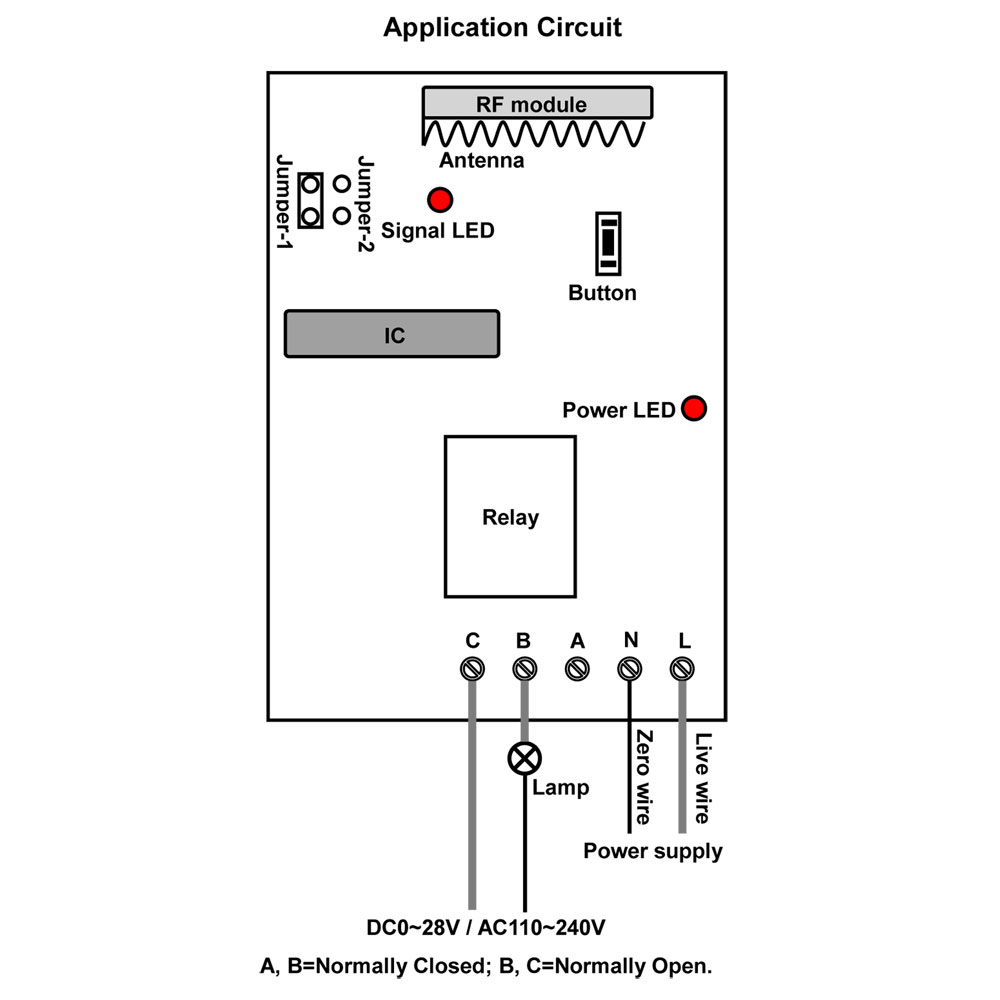
The delay time is set in advance. It is non-adjustable.

Press button 1: Turn on the relay (connect B and C, disconnect A and B)

After delay time, turn off the relay by itself (disconnect B and C, connect A and B)

During the delay time, press button 2: Turn off the relay straightway (disconnect B and C, connect A and B)

Two Single Channel Transmitters Remote Control Two Relays on One Receiver

Question from customer:

I need a 2 channel receiver with 2 remotes 1 channel. One remote control activates the channel A receiver on the receiver and another remote to turn on the channel B on the receiver. Is it possible with the CWB-1 model? And which receiver would like to recommend?

Answer:

We recommend 2 channel 12V multi-mode receiver (S2U-DC12) and two waterproof wireless 50m remotes (CWB-1). We set configured code for them so that they can work together. The receiver is 12V activated and has two relays. When it works with that transmitter, its transmission distance can reach 50m in the open air. There is only one button on each transmitter.

It can control lights, motors, fans, electrically operated doors / locks / windows / blinds / cars or other appliances with AC110~240V or DC0~28V. You can turn on/off the receiver with transmitter (remote control) from any place within a reliable distance; the wireless RF signal can pass through walls, floors, doors and other obstacles.

remote-controller_1

We will take a dc lamp wiring method as an example.

A,B terminals is normally closed. B,C terminals is normally open.

Wire two lamps to B&C terminals of each relay. Do as following picture shown.

receiver

Usage:

Setting control mode Toggle: Only connect Jumper-2.

Press the first remote -> lamp 1 is On; Press the first remote again -> lamp 1 is Off.

Press the second remote -> lamp 2 is On; Press the second remote again -> lamp 2 is Off.


Setting control mode Momentary: Only connect Jumper-1.

Press and hold the first remote -> lamp 1 is On; Release the first remote -> lamp 1 is Off.

Press and hold the second remote -> lamp 2 is On; Release the second remote -> lamp 2 is Off.


Setting control mode Latched: Disconnect Jumper-1 and Jumper-2.

Press -> On, another relay Off; Press another button -> Off.


Setting control mode Momentary + Toggle: Connect Jumper-1 and Jumper-2.

Control mode Momentary (Channel 1): Press -> On; Press again -> Off.

Control mode Toggle (Channel 2): Press and hold -> On; Release -> Off.

Wireless remote control 4 DC 12V motors within 2000m/6000ft

We recommend the wireless device of long range remote control motor. It is model: S4C-DC12-ANT2 & CB-4L. The receiver (S4C-DC12-ANT2) has 4 relays and can connect 4 DC appliances. The transmitter (CB-4L) can remote control the appliances on/off within 2000m/6000ft theoretically because of the external extend antenna in the receiver. Besides, the wireless device remote control lights, motors, fans, electrically operated doors/ locks/ windows/ blinds/cars or other appliances with AC110~240V or DC0~28V. For example, you can connect 4 DC motors to receiver.

receiver & transmitter

Here is the circuit diagram of receiver. You can connect 4 DC motors to C terminal of relays in the receiver. Then supply power DC 12V to receiver by connecting wires to positive pole and negative pole. You press one button of transmitter, one of four motors will turn on/off by wireless remote control.

circuit diagram

The wireless remote control device has four control modes: toggle, momentary, latched, momentary+toggle. You can choose any one of four control modes. We introduce momentary control mode here.

You only connect Jumper-1, it is momentary control mode.

Press and hold button A: Turn on motor 1 (connect B and C, disconnect A and B)

Release button A: Turn off motor 1 (disconnect B and C, connect A and B)


Press and hold button B: Turn on motor 2 (connect B and C, disconnect A and B)

Release button B: Turn off motor 2 (disconnect B and C, connect A and B)


Press and hold button C: Turn on motor 3 (connect B and C, disconnect A and B)

Release button C: Turn off motor 3 (disconnect B and C, connect A and B)


Press and hold button D: Turn on motor 4 (connect B and C, disconnect A and B)

Release button D: Turn off motor 4 (disconnect B and C, connect A and B)


Of course, you can also set other control modes according to the product’s instruction in our website.


Finally you can enter into the website and search the wireless remote control device as following:

Model: 0020510 (S4C-DC12-ANT2 & CB-4L)


Website:

http://www.carymart.com/4ch-2000m-5a-dc-long-distance-rf-remote-control-receiver-transmitter-learning-code-p-1537.html


http://www.ourautomation.com/4ch-2000m-5a-dc-long-distance-rf-remote-control-receiver-transmitter-learning-code-p-1537.html

Boat Bridge is Controlled by Remote Controlled Electric Hoist

Question from customer:

“I’d like to order a 220v electric hoist to raise and down a bridge boat with a remote control. The ascent and descent should be done when someone is still pressing the remote control button, as there is no stop. What would you like me the most suitable product? Thank you in advance.”

electric hoist

Answer:

We recommend the ac 100V~240V momentary motor controlling model (S1FM-AC220 & CV-2-2). It is specially designed for motor controlling because two relays are inserted inside. One relay is used for motor rotating towards “UP”. Another relay is used for motor rotating towards “DOWN”. There are “UP”, “COM” and “DOWN” contacts from output terminal. This kit can controls motor of rolling blinds, doors, projection screens, awnings, pumps, conveyors other appliances and mechanicals. The transmitting distance is usually about 500m in the open air.

motor controller

Wiring:

Connect live wire to terminal “L” and neutral wire to terminal “N”. Then connect AC electric hoist motor to terminals “UP”, “COM” and ‘DOWN”. You can exchange “UP” and “DOWN” wires of motor to change rotating direction of motor.

wiring

Operation:

There are three buttons on the receiver for motor up and down. But button ■ on the receiver is useless.

Press and hold button ▲ on remote or receiver: Terminals UP and COMMON directly output AC110V / AC220V; electric hoist motor rotates continuously in positive direction.

Release button ▲ on remote or receiver: Stop the electric hoist motor.

Press and hold button ▼ on remote or receiver: Terminals DOWN and COMMON directly output AC110V / AC220V; electric hoist motor rotates continuously in reversal direction.

Release button ▼ on remote or receiver: Stop the electric hoist motor.

Retrieving Motion Detector by 1 Channel 12V Radio Module

Question from customer:

I want a kit radio module 1 channel (12V), can transmit the state of a dry contact input (on transmitter). This is to retrieve the status of a motion detector. Distance 60m open field.

Answer:

We recommend 1 channel 12V rf receiver and transmitter with dry contact input (S1L-DC12-ANT2 & CB-2N). The very special design is its transmitter with a dry contact input aside. The triggering method of this transmitter is connection of two wires on it. There is only one channel at that relay on the receiver. The output contacts of relay are normally open and closed. Working distance of transmitter and receiver with external extend antenna are 2000M / 6000ft (theoretically).

remote controller

Wiring:

Wires on the transmitter should be connected to the contacts of motion detector (original device).

The normally open contacts B&C of receiver should be connected to the device being controlled.

Maybe you can wire a lamp to the receiver. We offer three voltage versions for receiver: 9V, 12V and 24V. You can choose the right one according to the voltage of device being controlled.

wiring diagram

wiring-of-transmitter

Operation:

When the motion detector (original device) is triggered and begin to work, the transmitter is also triggered and then transmits an rf signal “ON” to the receiver. After the receiver receives the signal, contacts B&C are closed; the lamp being controlled will be turn on.

When the motion detector (original device) is not triggered and stop working, the transmitter is also triggered and then transmits an rf signal “OFF” to the receiver. After the receiver receives the signal, contacts B&C are cut; the lamp being controlled will be turn off.


Note:

The output contacts of motion detector should be normally open / normally closed.

Buttons on the remote are only used for test.

The big button is for testing “ON” signal. The small button is for testing “OFF” signal.