Two Single Channel Transmitters Remote Control Two Relays on One Receiver

Question from customer:

I need a 2 channel receiver with 2 remotes 1 channel. One remote control activates the channel A receiver on the receiver and another remote to turn on the channel B on the receiver. Is it possible with the CWB-1 model? And which receiver would like to recommend?

Answer:

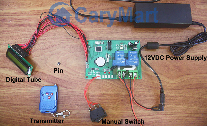
We recommend 2 channel 12V multi-mode receiver (S2U-DC12) and two waterproof wireless 50m remotes (CWB-1). We set configured code for them so that they can work together. The receiver is 12V activated and has two relays. When it works with that transmitter, its transmission distance can reach 50m in the open air. There is only one button on each transmitter.

It can control lights, motors, fans, electrically operated doors / locks / windows / blinds / cars or other appliances with AC110~240V or DC0~28V. You can turn on/off the receiver with transmitter (remote control) from any place within a reliable distance; the wireless RF signal can pass through walls, floors, doors and other obstacles.

remote-controller_1

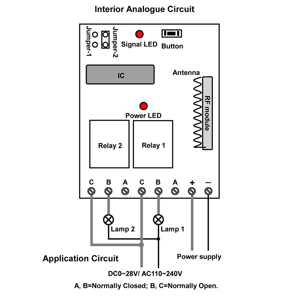
We will take a dc lamp wiring method as an example.

A,B terminals is normally closed. B,C terminals is normally open.

Wire two lamps to B&C terminals of each relay. Do as following picture shown.

receiver

Usage:

Setting control mode Toggle: Only connect Jumper-2.

Press the first remote -> lamp 1 is On; Press the first remote again -> lamp 1 is Off.

Press the second remote -> lamp 2 is On; Press the second remote again -> lamp 2 is Off.


Setting control mode Momentary: Only connect Jumper-1.

Press and hold the first remote -> lamp 1 is On; Release the first remote -> lamp 1 is Off.

Press and hold the second remote -> lamp 2 is On; Release the second remote -> lamp 2 is Off.


Setting control mode Latched: Disconnect Jumper-1 and Jumper-2.

Press -> On, another relay Off; Press another button -> Off.


Setting control mode Momentary + Toggle: Connect Jumper-1 and Jumper-2.

Control mode Momentary (Channel 1): Press -> On; Press again -> Off.

Control mode Toggle (Channel 2): Press and hold -> On; Release -> Off.

Manual Switch and Transmitter of Digital Tube Circuit with Timed Controlling Function Control Motor

Digital tube circuit controller is 12VDC power activated. And motor can be wired to output terminals. The receiver and controlled device can share the same power supply. You can use manual switch or transmitter to remote control motor. In addition, with timing control function, you can preset designated time and when time is up, motor will rotate or stop automatically.

digital tube circuit board

Here we talk about using the manual switch and transmitter to control motor.

Manual switch controlling:

Control positive, reverse rotation and stop of motor.

Working method: Move to “positive rotation” position, motor rotates in positive direction; move to “Stop” position, motor stops; move to “reverse rotation” position, motor rotates in reverse direction.

Remote Control with transmitter:

Insert pin to jumper: Press and hold the “▲” button, motor rotate in positive rotation; release the “▲” button, motor stops. Press and hold the “▼” button, motor rotates in reverse direction; release the “▼” button, motor stops.

Do not insert pin to jumper: Press the “▲” button, motor rotate in positive rotation; press the “■” button, motor stops. Press the “▼” button, motor rotates in reverse direction; press the “■” button, motor stops.

Here two videos for your reference.

Manual switch controlling:

Remote Control with transmitter:

How to Remote Control Two Gates Open and Close

Question from customer:

I am looking for a transmitter and receiver with at least 3 buttons (4 max ) to be used to open and close my gate. I don’t know which is better RF or UHF? Do you have anything that can work for me? I will do the electronics all I need is the option to latch or momentary relay outputs.

Answer

We recommend 4 channel 12V multi-mode remote controller (S4C-DC12+C-4). It operates in toggle, momentary, latched and toggle + momentary control mode (set the mode as you like freely). You can use it to complete four operations at the same time. For example, turn the light on, open the door or control other dc/ac electrical devices in the meantime. It is applied for light remote control, motor remote control, garage door remote control, gate remote control, etc. We think this remote can be used for controlling gate. That is to say, you can use this remote control to control one or two motors of your gate. To realize gate opening and closing, one motor needs two relays to support.

1_03

Secondly, it is the wiring. Suppose you have two gates to remote control. We will wire motors to receiver according to the wiring diagram. B is the common terminal. A is the closed terminal and C is the open terminal. Usually, one relay can only switch on and off one motor. So each two relays can control one motor rotate in positive and reverse direction. We connect two motors to B terminals to every two relays respectively. Connect terminal C to the positive and connect terminal A to the negative.

application circuit

We choose momentary working mode: only connect Jumper-1. (We usually use momentary mode for motor controlling. Or you can also choose latched mode if you want.)

Press and hold button 1, motor 1 rotates in positive direction, gate 1 is opening. Release button 1, motor 1 stops.

Press and hold button 2, motor 1 rotates in reverse direction, gate 1 is closing. Release button 2, motor 1 stops.

Press and hold button 3, motor 2 rotates in positive direction, gate 2 is opening. Release button 3, motor 3 stops.

Press and hold button 4, motor 2 rotates in reverse direction, gate 2 is closing. Release button 4, motor 2stops.

One Transmitter Remote Controls 12 Christmas Decorative LED Lamps

Question from customer:

When Christmas Day comes, people always use LED lights to decorate house or Christmas trees. So  I’m looking for a wireless remote that I can use to create a simple on off switch to 12 led light fixtures connecting to a 12V battery at different places around my home. That souds a good idea, right?  Do you have a recommendation for which Wireless remotes or RF transmitters may be the best for the task at hand?

LED Decoration

Answer:

We recommend model 12 Channel DC12V Remote Controller – 1 Transmitter & 12 Receiver (12S1UB-DC12&1CV-12). This RF remote controller has the special ability to learn remote codes, allowing it to be used in one-transmitter-to-many-receivers system. That is to say, you only need a transmitter to control 12 receivers. It operates in toggle, momentary, and latched mode (set the mode as you like freely). It is great for hard to reach lights or other DC/AC electrical devices, remote distance can be 500m (theoretically). And it is applied for controlling lights, motors, fans, electrically operated doors / locks / windows / blinds / cars or other appliances with voltage AC110~240V or DC0~28V.

1_01

Here is the wiring diagram. LED lamp is connected to normally open terminals B&C. And add a wire between terminals “B&-“ and another wire to terminals “C&+”. At last, wire a plug to terminals “+&-“.

circuit

It’s easy to set and operate. You can press each button on the transmitter to control the corresponding receiver to control LED lamp. The receiver can learn at most 60 different codes for remote controlling.

100M RF Wireless Remote Switch for Solenoids and Linear Motors

Question from customer:

I need to remotely control two on/off solenoids and two linear actuators on my truck. They are all actuated by 24V power supply in my truck. Do you have a system that will do this?

solenoid valvesolenoid valve

linear actuator in truck COPY

Answer:

We recommend the model of 4 channel multi-mode 24V remote control (S4U-DC24+C-4). This kind of remote control is 4 channels with multi-modes, which includes toggle, momentary, latched and momentary+toggle. It is flexible choice for you. You can choose the 24V actuated remote control since there is 24V power in your truck. The working distance is about 100M.

remote control

Then connect 2 linear actuators to channel 1 and 2 in parallel, connect two on/off solenoids to channel 3 and 4 respectively. You can set the receiver to Momentary (Channel 1~2) + Toggle (Channel 3~4) control mode.

The wiring is just a little complicated. Please see the wiring diagram below, B is common terminal. Each linear actuator motor is supposed to be connected to B terminals of relay 1&2. A is normally closed terminal and C is normally open terminal. Connect terminal C to the positive and connect terminal A to the negative. Each solenoid is connected to B&C terminals of relay 3&4.

circuit

After wiring, you can control them by the transmitter C-4.

Press and hold button 1, linear actuators move forward together, release the button 1, linear actuators stop together.

Press and hold button 2, linear actuators move backward together, release the button 2, linear actuators stop together.

Press button 3, turn on solenoid 1. Press button 3 again, turn off solenoid 1.

Press button 4, turn on solenoid 2. Press button 4 again, turn off solenoid 2.