DC Motor Rotation Automation

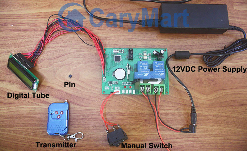
We have set and saved the following data previously:

15:10  Motor rotates in positive direction. (The first operation), that is (W:3  C:1  R:+ WORK).

15:11  Motor stops. (The second operation), that is(W:3  C:2  R:0 WORK).

15:12  Motor rotates in reverse direction.(The third operation), that is (W:3  C:3  R:- WORK).

15:13  Motor stops. (The fourth operation), that is(W:3  C:4  R:0 WORK).

Everything is done. DC motor is ready to work when time is up.


When the real time is 15:10, motor rotates in positive direction. At the bottom of the tube screen, it displays the next operation at this time.

W:3 (Wednesday)  C:2 (The second operation)  R:0(stop) WORK

When the electronic clock reads 15:11, motor will stop.

positive-rotation

When the real time is 15:11, motor stops. At the bottom of the tube screen, it displays the next operation at this time.

W:3 (Wednesday)  C:3 (The third operation)  R:- (reverse direction) WORK

When the electronic clock reads 15:12, motor will rotate in reverse direction.

stop 1

When the real time is 15:12, motor rotates in positive direction. At the bottom of the screen, it displays the next operation at this time.

W:3 (Wednesday)  C:4 (The fourth operation)  R:0(stop) WORK

When the electronic clock reads 15:13, motor will stop.

reverse-rotation

When the real time is 15:13, motor stops. All operations are finished successfully.

stop 2

Vdieo:

Motor Automation Time Setting

We’d like to do time setting of motor rotation and stop automatically. We still use button S1~S3 to set or adjust time.

Suppose that the real time is February, 19th 2014, 15:00, Wednesday.

We will set the following data:

15:10, Wednesday, motor rotates in positive direction

15:11, Wednesday, motor stops

15:12, Wednesday, motor rotates in reverse direction

15:13 Wednesday, motor stops

Procedure:

Press and hold S1 (about 2 seconds) to enter into automatic working setting.

Press S1 again to set “Week (W)”, press S2/S3 to set W:3;

Press S1 again to set “Working times (C)”, press S2/S3 to set C:1(The first working time), C:2 (The second working time)…;

Press S1 again to set “Motor working status (R)”, press S2/S3 to set R+ /- / 0 (+ : motor positive rotation, -: motor reverse rotation, 0: motor ‘s stop)

Press S1 again to set “Motor working time”, press S2/S3 to set time of motor working status (e.g.15:10)

Press and hold S1 about 2 seconds to finish this setting and saving data.

(When you press S2/S3 to adjust data, the corresponding figure will flicker)


Finishing and saving the first setting data(15:10, Wed, Positive rotation) :

The screen reads “2014-02-19  15:02  W:3  C:1  R:+ Work”

(15:02 is the real time; W:3 is Wednesday;  C:1 is the first working time; R:+ is positive rotation)

positive rotation

Finishing and saving the second setting data(15:11, Wed, Stop):

The screen reads “2014-02-19  15:02  W:3  C:2  R:0 Work”

(15:02 is the real time; W:3 is Wednesday;  C:2 is the second working time; R:0 is motor’s  stop)

stop 1

Finishing and saving the third setting data(15:12, Wed, Reverse rotation):

The screen reads “2014-02-19  15:03  W:3  C:3  R:- Work”

(15:03 is the real time; W:3 is Wednesday;  C:3 is the third working time; R:- is reverse rotation)

reverse rotation

Finishing and saving the fourth setting data(15:13, Wed, Stop):

The screen reads “2014-02-19  15:04  W:3  C:4  R:0 Work”

(15:04 is the real time; W:3 is Wednesday;  C:4 is the fourth working time; R:0 is motor’s stop)

stop 2

Video:

Manual Switch and Transmitter of Digital Tube Circuit with Timed Controlling Function Control Motor

Digital tube circuit controller is 12VDC power activated. And motor can be wired to output terminals. The receiver and controlled device can share the same power supply. You can use manual switch or transmitter to remote control motor. In addition, with timing control function, you can preset designated time and when time is up, motor will rotate or stop automatically.

digital tube circuit board

Here we talk about using the manual switch and transmitter to control motor.

Manual switch controlling:

Control positive, reverse rotation and stop of motor.

Working method: Move to “positive rotation” position, motor rotates in positive direction; move to “Stop” position, motor stops; move to “reverse rotation” position, motor rotates in reverse direction.

Remote Control with transmitter:

Insert pin to jumper: Press and hold the “▲” button, motor rotate in positive rotation; release the “▲” button, motor stops. Press and hold the “▼” button, motor rotates in reverse direction; release the “▼” button, motor stops.

Do not insert pin to jumper: Press the “▲” button, motor rotate in positive rotation; press the “■” button, motor stops. Press the “▼” button, motor rotates in reverse direction; press the “■” button, motor stops.

Here two videos for your reference.

Manual switch controlling:

Remote Control with transmitter:

30A High Power Remote Switch for Fireplace Chimney Fan

Question from Customer:

I’m looking for solution to remotely control fireplace chimney fan on roof of hi-rise building. Desired range would by over 150- 300ft. Fan is 110v, around 2A. Power source would be on roof and antenna would be on roof.

Please let me know if you have hardware solution.

fireplace chimney fan

Answer:

1 channel 30A long range remote switch (S1PX-AC220-ANT2&CB-2) is very suitable for you. With 30A current and AC100~240V voltage direct output, you don’t have to provide additional power supply to controlled fireplace chimney fan because it can get power from powered receiver. The receiver is installed a external extend magnetic antenna, it will help receiver to amplify RF signal reception so that its working distance can reach 2000m(6000ft) outdoor. It is applied to hi-rise building and long range between two buildings. The transmitter enhances its transmitting function to match this kind of receiver.

1

The wiring procedure is simple. Look at the following picture. Wire fan’s motor to L&N terminals of receiver. Supply 110v to receiver.

circuit

There are toggle, momentary, latched modes in it. Among three modes, we suggest you to use latched mode (Do not connect Jumper-1 and Jumper-2.)

Press big button: Turn on the fireplace chimney fan.

Press small button: Turn off the fireplace chimney fan.

500M Toggle Transmitter Remote Control 4 Lamps in House

Question from customer:

I’m looking for a wireless remote that I can use to create a simple on off switch to 4 AC lights fixtures for living room, bed room, kitchen, shower room’s illumination. Do you have a recommendation for which wireless remote or RF transmitters may be better choice for this task?

house illumination

Answer:

We recommend model 4Channel AC110V~220V Remote Controller – 1 Transmitter & 4 Receivers   (4S1T-AC110/220V+CV-4). The AC RF remote control switch system, which is one transmitter pairs with four receivers. With about 500 meters range (theoretically), it can widely used in lights / lamps , motors, fans, cameras, video signals, audio signals, garage doors, electric shutter doors, telescopic doors, windows, cars, etc. This remote control has a toggle control mode which is the only working mode in it. It is a low cost remote control with high quality. Extremely easy to install and use. The maximum current is 3 ampere each channel.

1

The light wiring is fairly simple.

Connect the neutral wire to the terminal “1”, and the live wire to the terminal “2”. Connect the lamp to the terminal “5” and the neutral wire. S o you can wire your lamps to each receiver one by one.

1_07

Operation procedure:

1) Press button 1, turn on the lamp of receiver 1. Press button 1 again, turn off the lamp of receiver 1.

2) Press button 2, turn on the lamp of receiver 2. Press button 2 again, turn off the lamp of receiver 2.

3) Press button 3, turn on the lamp of receiver 3. Press button 3 again, turn off the lamp of receiver 3.

4) Press button 4, turn on the lamp of receiver 4. Press button 4 again, turn off the lamp of receiver 4.

Holding one transmitter, you can wireless remote control your any controlled lamps of house easily because the wireless signal can pass through walls, floors and doors with reliable distance.