We are about to recommend remote controller which is applied to both motor and lamp. It is DC12V momentary &toggle remote controller (S1F-DC12 & C-3-2), which features in motor forward-reverse capability. You can rotate the motor in positive or reversal direction by transmitter from any place within a reliable distance, wireless signal pass through walls, floors and doors. It is suitable for the motors of rolling blinds / doors, projection screens, awnings, pumps, winches, conveyors or other appliances and mechanicals with voltage DC12V. We also design lamp controlling function so that you can control motor and lamp with the same transmitter.
Month: July 2014
 Follow
Water Pump Motor Automation
When you want to remote control your water pump from a long distance with controller or let your water pump work automatically with the help of water level sensor, we think our item-water pump motor automatic control system will help you. This system includes a long range remote receiver (S1PUA-AC220-ANT2), two transmitters (CB-2/CB-2N-2) and two water level sensors.
It can control AC110~240V water pump motors by manual controller or automation with water level sensor.

We will build this water motor automatic control system.
Here is the wiring of receiver and water motor. Wire motor to A terminal and N terminal. Using a wire to connect B terminal and L terminal. And one wire connect N terminal, another wire connect L terminal.

Here is the installation of transmitter and water level sensor.
Put the water level sensor 1 downwards to the low water level position; Put the water level sensor 2 upwards to the high water level position.
Two wires of the water level sensor 1 are connected to wire 1 and wire 3 of transmitter CB-2N-2.
Two wires of the water level sensor 2 are connected to wire 2 and wire 3 of transmitter CB-2N-2.
Note: Triggering method of transmitter (CB-2N-2): connection to wire 1 and wire 3, it will send signal “ON”, connection to wire 2 and wire 3, it will send signal “OFF”.

Operation:
When water reaches the low water level, two wires of the water level sensor 1 is connected and the transmitter is triggered. The transmitter will send an ‘ON”’ signal to the receiver. The receiver will instruct the water pump motor to pump water into the tank.
When water reaches the high water level, two wires of the water level sensor 2 is connected and the transmitter is triggered. The transmitter will send an “OFF” signal to the receiver. The receiver will instruct the water pump motor to stop pumping water.
Mobile Phone Remote Control Linear Actuator Motor
We’d like to introduce another kind of mobile phone WiFi controllers-8 Channels AC or DC 30A High Power Output WiFi controller (WF-8-2R). This WiFi controller is 8 channels AC or DC 30amps output, so you can use it to remote control high power device. We will show you how to remote control linear actuator.

Here is the material we prepared.
1×WIFI controller (WF-8-2R)
1×mobile phone
1×12VDC Linear Actuator Motor
1×9VDC 1A Power Adapter (for WIFI controller)
1×12VDC 6A Power Adapter (for linear actuator )
Wires

The WiFi controller has ac/dc power output terminals. The wiring looks like this.
Brown wire of linear actuator is wired to Output 1, blue wire of linear actuator is wired to Output 2. Wire 12VDC 6V power adapter to Input terminals of controller and 12VDC 1A power adapter to power supply terminal of controller.


After switching on power, the first LED is on. This is the power LED. Waiting for a while, we connect mobile phone WiFi when the WIFI start-up LED shines (the second LED). After a while, WiFi connection status LED shines when the WiFi connection is successful. We press control software icon which is installed in the mobile phone in advance to enter operated status. And press the “connect” from the top right corner.
![]()
Set Momentary control mode for relay 1 and relay 2: Click the ▼ icon of 1&2 channels. Choose M (Momentary) control mode for each channel.

Press and hold button 1, motor shaft extends. Release button 1, motor shaft stops.

Press and hold button 2, motor shaft retracts. Release button 2, motor shaft stops.

Video:
How to Remote Control 4 AC Lamps Off/On
2000M long range 4CH AC power output remote control kit (S4X-AC220-ANT2+CB-4L) is recommended here. 4-button transmitter is compatible with 4 channel receiver. One button is to its correspondent channel. You can connect 4 lamps to receiver. This remote is 220VAC power output so you have not to supply any power to controlled lamps. With external extended antenna, the transmission distance reach 2000m in the open field.

Here is the wiring diagram. You can connect 4 AC lamps to “A&B” output terminals of receiver. Then supply power to receiver.

Setting “Toggle Mode” Only connect Jumper-2 with a little jumper.
Press button A, turn on lamp 1; Press button A again, turn off lamp 1.
Press button B, turn on lamp 2; Press button B again, turn off lamp 2.
Press button C, turn on lamp 3; Press button C again, turn off lamp 3.
Press button D, turn on lamp 4; Press button D again, turn off lamp 4.

Remote Controller is Applied to LED Lamp for Decoration
When you use led lamps to decorate your bed room, your balcony, your garden, your yard or do something glowing Christmas lighting ornament outdoor, you must be very tired with complex wiring, we try to make those wiring procedure easier.

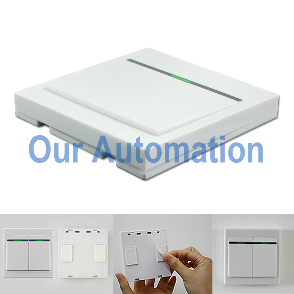
A wireless wall-mounted switch and dc output receiver can be a new remote control unit (S1X-DC12&HR-1). It is dc power output so you can use it to control DC 0~28V actuated electrical devices off/on. This wall mounted switch is like ordinary wall switch from appearance, but it is wireless and operated by RF signal that can pass through walls, floors and doors. It is be affix to any place you want by double faced adhesive tape. The switch works with DC power output receiver, you LED lamps can wired to output terminals of receiver and also get power from them.
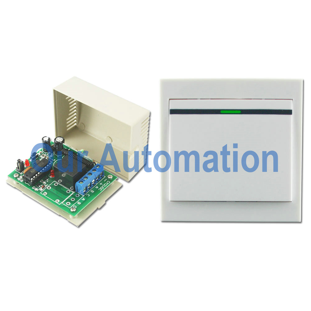
Here is the wiring diagram.
Wire dc led lamp to OUTPUT of receiver. And add power supply to receiver. This kind of receiver is designed for DC output terminals so that lamp can get power from output terminals of receiver directly as mentioned above.

Setting different control modes (We usually set toggle for lamp controlling.)
Setting control mode Toggle: Only connect Jumper-2.
Press button: Turn on the relay, terminal OUT outputs DC power, turn on led lamp.
Press button again: Turn off the relay, terminal OUT no output, turn off led lamp.