Wireless Wall-Mounted Switch Remote Control Kit for AC Lamp

We made a remote control kit which consists of a wall-mounted switch and a remote receiver (S1X-AC220&HR-1).

wall-mounted switch and receiver

When we use ordinary switch to switch home appliances off and on, we should do some wiring for home appliances, some time it is very complicated and time- consuming. Our RF wireless wall mounted switch looks like universal switch from appearance, but it is wireless and operate by RF signal that can pass through walls, floors and doors. It is can be simply affix to any place you want by double faced adhesive tape.

wall-mounted switch

Through RF signal, you don’t have to wire between switch and appliances. Wall-mounted switch works with remote receiver to remote control ac lamp.

Here is the wiring diagram.

wiring diagram

Wire ac lamp to OUTPUT of receiver. And add power supply to receiver. This kind of receiver is designed for AC output terminals so that lamp can get power from output terminals of receiver directly.

Setting different control modes (We usually set toggle for lamp controlling.)

Setting control mode Toggle: Only connect Jumper-2.

Press button: Turn on the relay, terminal OUT outputs AC power, turn on lamp.

Press button again: Turn off the relay, terminal OUT no output, turn off lamp.

How to Control Linear Actuator by Remote Transmitter and Manual Switch

30 amps dc output controller (S1PF-DC12-ANT2+CB-4) is designed for motor controlling. It is compatible with many kinds of motor which is actuated by DC 12V/24V. It is applied to DC motors of rolling blinds / doors, projection screens, awnings, pumps, winches, conveyors or other appliances. We add external extended antenna to the receiver, so we make its transmitting distance reach to 2000m (6000ft) in the open field. The receiver pairs up with a 4-button transmitter and has manual switches on itself. Both transmitter and manual switches can send signal to receiver.

remote controller

Let’s show you how to control 12V DC linear actuator with transmitter and manual switch.

Here is the material.

1×receiver: S1PF-DC12-ANT2

1×transmitter: CB-4

1×12VDC Linear Actuator Motor

Power supply : 12VDC 3A Power Adapter

material

Wiring is simple. You should wire linear actuator to OUTPUT terminal of receiver.

wiring

Setting control mode Latched: Connect Jumper (CN1)

Press button “A”, motor shaft extends

Press button “C”, motor shaft retracts

Press button “B” or ‘D”, motor stops

motor shaft extendmotor shaft retract

motor stop

Manual Switch (Latched mode)

Press “S1″, motor shaft extends

Press “S3″, motor shaft retracts

Press “S2″, motor stops

S1 extendS3 retract

S2 stop

Setting control mode Momentary: Do not connect Jumper

Press and hold button “A”, motor shaft extends; Release button “A”, motor stops

Press and hold button “C”, motor shaft retracts; Release button “C”, motor stops

S1 extendS3 retract

Manual Switch (Momentary mode)

Press and hold button “S1″, motor shaft extends; Release button “S1″, motor stops

Press and hold button “S3″, motor shaft retracts; Release button “S3″, motor stops

motor shaft extendmotor shaft retract

www.ourautomation.com


One Transmitter Remote Control 4 Devices Actutated by 24 V and 240V Version

Question from customer:

Whether we can get the receivers with different voltage versions? For example 2 piece of 24 volt and 2 piece of 240 volt.

Answer:

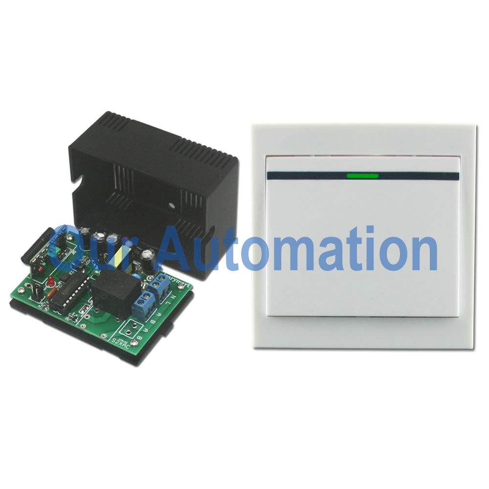
Yes, it is possible. We recommend those two kinds of receivers—for 24V version, it is 24V DC input receiver (S2UB-DC24). For 240V version, it is 100V~240V input receiver (S2U-AC220). Both of them have two relays on the PCB. So there are four channels totally for your devices. They can pair up with long range transmitter (CB-4).

remote-controller

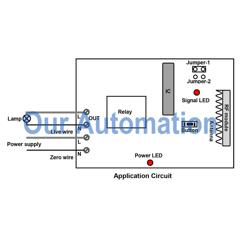
It can control lights, motors, fans, electrically operated doors/locks/windows/blinds/cars or other appliances with voltage AC 110~240V or DC 0~28V. Owing to normally open& closed contact, you should add additional power supply to your devices besides your receivers. But you can do as following wiring method to save power supply adaptors. Wire devices (lamps) to B terminals of each relay, using wires to connect devices to output terminals of each receiver. For dc input receiver, we supply dc 24v power; for ac input receiver, we supply ac 240v power.

circuit

There are toggle, momentary, latched and momentary+toggle modes. You want to remote control 4 devices, so you’d better choose toggle or momentary mode or toggle+momentary mode.

Setting control mode Toggle: Only connect Jumper-2.

Control mode Toggle: Press -> On; Press again -> Off.

Press button A: Turn on relay 1 of Receiver 1 (connect B and C, disconnect A and B)

Press button A again: Turn off relay 1 of Receiver 1 (disconnect B and C, connect A and B)

Press button D: Turn on relay 2 of Receiver 2 (connect B and C, disconnect A and B)

Press button D again: Turn off relay 2 of Receiver 2 (disconnect B and C, connect A and B)

Setting control mode Momentary: Only connect Jumper-1.

Control mode Momentary: Press and hold -> On; Release -> Off.

Press and hold button A: Turn on relay 1 of Receiver 1 (connect B and C, disconnect A and B)

Release button A: Turn off relay 1 of Receiver 1 (disconnect B and C, connect A and B)

Press and hold button D: Turn on relay 2 of Receiver 2 (connect B and C, disconnect A and B)

Release button D: Turn off relay 2 of Receiver 2 (disconnect B and C, connect A and B)

Setting control mode Momentary + Toggle: Connect Jumper-1 and Jumper-2.

Control mode Momentary (Channel 1 of Receiver 1, 2): Press and hold -> On; Release -> Off.

Press and hold button A: Turn on relay 1 of Receiver 1 (connect B and C, disconnect A and B)

Release button A: Turn off relay 1 of Receiver 1 (disconnect B and C, connect A and B)

Press and hold button B: Turn on relay 1 of Receiver 2 (connect B and C, disconnect A and B)

Release button B: Turn off relay1 of Receiver 2 (disconnect B and C, connect A and B)

Control mode Toggle (Channel 2 of Receiver 1, 2): Press -> On; Press again -> Off.

Press button C: Turn on relay 2 of Receiver 1 (connect B and C, disconnect A and B)

Press button C again: Turn off relay 2 of Receiver 1 (disconnect B and C, connect A and B)

Press button D: Turn on relay 2 of Receiver 2 (connect B and C, disconnect A and B)

Press button D again: Turn off relay 2 of Receiver 2 (disconnect B and C, connect A and B)

How to Remote Control 24 Lamps with One Transmitter

99-channel Transmitter pairs up with 24 receivers to build a remote control kit (24S1XCB-AC220 & CP-99). It can controls lights, fans, motors, electrically actuated doors/ locks/ windows/ rolling blinds/ cars or other appliance with AC 110~240V. The transmitter adopts singlechip technology to build million of code and has LCD display screen. One transmitter can work with 99 receivers simultaneously.

remote controller-our automation1_10

This kind of remote controller aims at controlling 24 AC Lamps. We will show you the procedure.

circuit-our automation

circuit-diagram

Step 1

Wire each lamp to terminals 1 &5 of each receiver. And supply power to each receiver.

Step 2

The coding type is learning code, so receiver should learn from transmitter at first.

1) Press and hold the button of receiver about 2 seconds until signal LED flashes; then release the button, at this time the receiver enters into status of LEARNING.

2) Press any number button on the transmitter to select a number from 01 to 99, then press button “T” or “M” to send signal. If signal LED immediately turns off, it means learning is successful.

3) The receiver can learn only one channel of the transmitter. So learning code must be one by one till the last one.

Step 3

Press any number button to select a number from 01 to 99 by combination of the number 0~9, then press button “T” (Toggle) or “M” (Momentary) to send signal. LCD screen will displays numbers at the same time, and LCD screen will turn off after 15 seconds if there is no any operation.

Toggle Mode Operation: If you want to send signal of the 24 channel, you can press “2″, then press “4″, next press button “T”, the signal is sent immediately; when you press the button “T” again, the signal will be sent again.

Momentary Mode Operation: If you want to send signal of the 24 channel, you can press “2″, then press “4″, next press and hold button “M”, the signal is continuously sent; when you release the button “M”, the signal will stop.

So we want to remote control 24 AC lamps, we choose Toggle mode.

Press 1+T, send signal to receiver, turn on lamp 1, press T again, turn off lamp 1. (Waiting for LCD screen being off, you can continue next operation every time.)

Press 2+4+T, send signal to receiver, turn on lamp 24, press T again, turn off lamp 24.

WIFI Controller and Mobile Phone Remote Control Linear Actuator

A linear actuator is an actuator which creates motion in straight line and applied in machine tools, industry, valves, disk driver, dentist’s chair… Maybe, it will be used at home, such as massage chair, electric sky lights, truck… Have you ever thought that you can use mobile phone to remote control your linear actuator motor in WIFI network? Absolutely you can do it with help of our mobile phone WIFI controller. Also we have linear actuator. We will show you how to realize that remote controlling procedure. Here is the material we should prepare.

1×WIFI controller (WF-8-1R)

1×mobile phone

1×12VDC Linear Actuator Motor

1×9VDC 1A Power Adapter (for WIFI controller)

1×12VDC 3A Power Adapter (for linear actuator )

Wires

material-our automation

The WIFI controller is normally open/ closed contact. The wiring is like this.

A, B terminals are normally closed; B, C terminals are normally closed. Two wires of linear actuator are wired to common terminals B of relay 1 and relay 2 respectively. C terminals are supposed to wire to positive pole of power adaptor. B terminals are supposed to wire to negative pole of power adaptor.

wiring diagram-our automation

wiring-our automation

After switching on power, the first LED is on. This is the power LED. Waiting for a while, we connect mobile phone WiFi when the WIFI start-up LED shines (the second LED). After a while, WiFi connection status LED shines when the WiFi connection is successful. We press control software icon which is installed in the mobile phone in advance to enter operated status. And press the “connect” from the top right corner.

press wifi software icon-our automation

Set Momentary control mode for relay 1 and relay 2: Click the ▼ icon of 1&2 channels. Choose M (Momentary) control mode for each channel.

M mode-our automation

Press and hold button 1, motor shaft extends. Release button 1, motor shaft stops.

press and hold button 1-our automation

Press and hold button 2, motor shaft retracts. Release button 2, motor shaft stops.

press and hold button 2-our automation

Video