Twelve 6V/9V/12V/24V Receivers and 1 Transmitter Kit

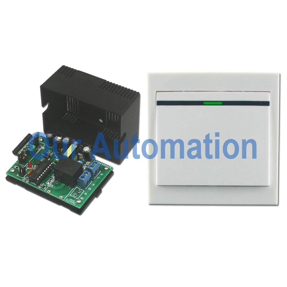
This rf remote controller (12S1UB-DC06/09/12/24 & CV-12 ) has the special ability to learn remote codes, allowing it to be used in one-transmitter-to-many-receivers system. It operates in toggle, momentary, and latched mode (switch modes as you like freely by connecting or disconnecting jumper). It is great for hard to reach lights or other DC/AC electrical devices, remote distance can be 500m (theoretically). Control lights, motors, fans, electrically operated doors / locks / windows / blinds / cars or other appliances with voltage AC110~240V or DC0~28V.

1_011_02

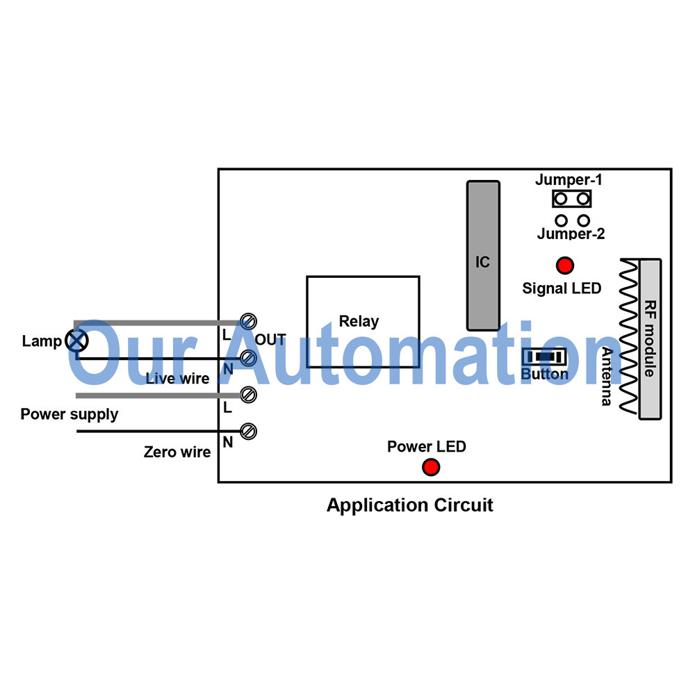
We’d like to show the wiring and controlling of ac, dc lamps or dc motors.

The contact of relay of each receiver is normally open/ closed. So you need to wire ac lamp to normally open contact B&C and supply AC 220V power to lamp. When you want to remote control dc motors or lamps, you can wire them to receivers as mentioned above. But dc motor and lamps can share the same power supply if you wire as the right picture shown.

circuit

Setting control mode Toggle: Connect Jumper-2.

Control mode Toggle: Press -> On; Press again -> Off.

Press button 1: Turn on Receiver 1 (connect B and C, disconnect A and B)

Press button 1 again: Turn off Receiver 1 (disconnect B and C, connect A and B)

Press button 12: Turn on Receiver 12 (connect B and C, disconnect A and B)

Press button 12 again: Turn off Receiver 12 (disconnect B and C, connect A and B)


Setting control mode Momentary: Connect Jumper-1.

Control mode Momentary: Press and hold -> On; Release -> Off.

Press and hold button 1: Turn on Receiver 1 (connect B and C, disconnect A and B)

Release button 1: Turn off Receiver 1 (disconnect B and C, connect A and B)

Press and hold button 12: Turn on Receiver 12 (connect B and C, disconnect A and B)

Release button 12: Turn off Receiver 12 (disconnect B and C, connect A and B)


Setting control mode Latched: Disconnect Jumper-1 and Jumper-2.

Control mode Latched: Press -> On, other relays Off; Press another button -> Off.

Press button 1: Turn on Receiver 1 (connect B and C, disconnect A and B)

Press other button: Turn off Receiver 1 (disconnect B and C, connect A and B)

Press button 12: Turn on Receiver 12 (connect B and C, disconnect A and B)

Press other button: Turn off Receiver 12 (disconnect B and C, connect A and B)

Wireless Wall-Mounted Switch Remote Control Kit for AC Lamp

We made a remote control kit which consists of a wall-mounted switch and a remote receiver (S1X-AC220&HR-1).

wall-mounted switch and receiver

When we use ordinary switch to switch home appliances off and on, we should do some wiring for home appliances, some time it is very complicated and time- consuming. Our RF wireless wall mounted switch looks like universal switch from appearance, but it is wireless and operate by RF signal that can pass through walls, floors and doors. It is can be simply affix to any place you want by double faced adhesive tape.

wall-mounted switch

Through RF signal, you don’t have to wire between switch and appliances. Wall-mounted switch works with remote receiver to remote control ac lamp.

Here is the wiring diagram.

wiring diagram

Wire ac lamp to OUTPUT of receiver. And add power supply to receiver. This kind of receiver is designed for AC output terminals so that lamp can get power from output terminals of receiver directly.

Setting different control modes (We usually set toggle for lamp controlling.)

Setting control mode Toggle: Only connect Jumper-2.

Press button: Turn on the relay, terminal OUT outputs AC power, turn on lamp.

Press button again: Turn off the relay, terminal OUT no output, turn off lamp.

Emergency Calling System with LED Display and Sound Alerting Function

A emergency calling button is used around a hospital bed that allows patients to alert a nurse or other hospital staff at the nurse’s station to know the patient’s need. For basic system, has nothing more than a button for patient. When the button is pressed, nurse is alerted by a light or an audible sound at nurse’s station. Now we integrate wireless calling button and wireless receiver host with LED display tube to build a brand new emergency calling system.

emergency button

Like basic system, this wireless type has ability for alerting nursing staff by sound, light or display rooms and beds’ messages in a terminal. This type has major advantage that is no wiring works while installation and reducing the costs. It’s much more mobile and handy than conventional system.

Our remote control calling system is the hi-tech electronic product which is integrated wireless communication and computer technology. It includes calling button and calling receiver. Each system has one calling receiver and many calling buttons. When there is a calling from a calling button, calling receiver will display corresponding number.

calling-button&receiver-host

We do some setting of this receiver host.

The First step:

Working mode setting:

Long press 2sec Button 1 of manager transmitter to enter settings mode; Use Button 3 or 4 to choose “Cd8”(Working mode setting) submenu. This display will show”0”, the press Button 3 or 4 to select the working mode.

Suppose we use it in the restaurant. So we select “4” (Hospital mode ). When you choose “4” mode, screen displays number 011 -999 for you to pair up with your calling button, sounds “Dingdong+Room 1-99+No.1 -9 emergency call”. After finish the setting , press button “2″ of manager transmitter to previous menu or quit to standby status.

Note : After finish the function, please power off and restart the host to ensure the function is comfired.


The second step :

Calling Transmitter pairing :

You can use calling transmitter control the receiver host, but you need pair them up at first.

Press Button 1 of manager transmitter for 2 sec to enter “Cd7″ submenu. Press Button 3 or 4 select one of the number, paired number must start from “011″ for calling button, and then press “Call” button on the transmitter, the speaker will sound “successful registration” and the display screen turn to next number “012″ automatically. Then you can continue to do the next pairing up to number 999 calling transmitter (hospital mode) if you need. After finish the pairing, press button “2″ of manager transmitter to previous menu or quit to standby status.

Note: 1) long press Button 3 or 4 of manager transmitter to jump the numbers quickly.

2) While the number is paired , the 4 corner LED indicators will be flicker, or not, if the LED indicators are off, it means that the number has no paired transmitter.

3) in hospital mode, this first two digits mean the room number from 01 to 99, the last one digit means the bed number in one room from 1 to 9, press “UP/DOWN” on the receiver to select suitable room and number.

Stick the calling button to wall or desk.

When patient needs emergency call, press the button, it will display “01  1” and sounds “Dingdong room 01 No. 1 emergency call”. It means room 1 bed 1 emergency call.