Wireless Calling System in Karaoke Rooms

Question from customer:

I want to run business of karaoke rooms. So I need a set to be installed in karaoke rooms and reception desk. It is better to install calling gadget to karaoke room and receiver to reception desk. When there is customer in karaoke room calling, he can using calling gadget to call our stall to help him. Do you have any suggestion?

Answer:

We recommend wireless calling system to you. It includes calling transmitter and receiver host. You can pair up any kinds of calling transmitter with receiver host according to your need. The receiver host is 999-channel, so you can pair up 999 transmitters with a 999-channel receiver host at most. This kit is multi-mode. It is better to choose “Normal mode”. You can choose 200m 2 buttons free sticker wireless calling button and a 999- channel receiver host and stick calling button on the wall of karaoke room.

Here we can show you this controlling project procedure.

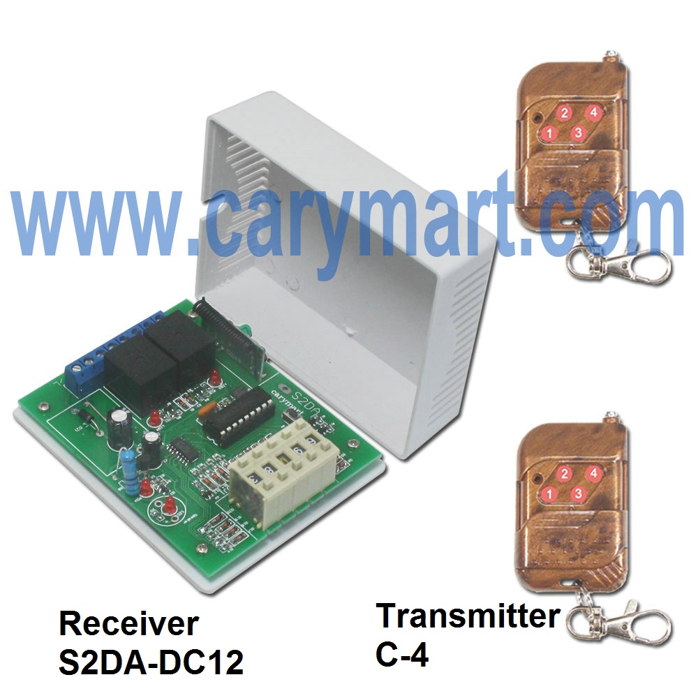
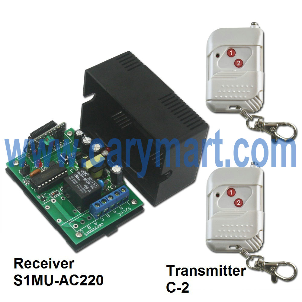
We prepare a receiver host, 2-button calling transmitters, manager remote and 9V power supply for receiver host.

our automation-wireless calling system-material

There are three steps to pair up transmitters and receiver host.

Working mode setting:

After switching on power, press and hold button 1 of manager remote for 2sec to enter setting menu, press button “3″ or “4″ to choose Cd8, press button 1 again to enter submenu of Cd8, press button “3″ or “4″ to choose “0″ (Mode 0: Normal mode), press button “2″ to turn back to setting menu.

our automation-wireless calling system 1

Calling button pairing:

Press button “3″ or “4″ to choose Cd7, press button 1 again to enter submenu of Cd7, press button “3″ or “4″ to choose “001″, Press any button of transmitter (except “Cancel”), the speaker will sound “successful registration” and 4 LED indicators will flicker. The display screen turn to next number “002″ automatically. Then you can continue to do the next pairing up the follow-up transmitter. Press button “2″ to turn back to setting menu.

our automation-wireless calling system 2

Key switch setting:

Press button “1″ to enter submenu of Cd6 to choose “2″(4-key mode). Press button “2″ twice to turn back to standby status.

our automation-wireless calling system 3

(After all the settings are finished, please power off the host and restart.)

Operation:

Press “Call”, screen reads “001” and sounds “Dingdong+No.1 call”.

Press “Cancel”, cancel previous call and turn back to standby status.

our automation-wireless calling system 4

Video:

https://www.youtube.com/watch?v=tfGhpxOdbzk&feature=youtu.be

200M 3 Buttons Free Sticker Wireless Calling Button & Receiver Host Operation

Question from customer:

Recently, I am ready to manager a large new restaurant. I want to divide it into different areas so as to be convenient to customers and waiters. So I need some calling system to be used in restaurant for customers and waiters. The transmitter can be used by customer. The receiver can be put to reception desk. When there is customer calling from any area, he can press the button to notify the waiter and customer will get help as soon as possible.

Answer:

We recommend wireless calling system. They include a 999-channel receiver host. You can choose this 3-button calling transmitter. That is to say, you can pair up 999 transmitters with a 999-channel receiver host at most. This kit is multi-mode. According to your requirement, you can choose “Area mode”.

We prepare a receiver host, 3-button calling transmitters, manager remote and 9V power supply for receiver host.

There are three steps to pair up transmitters and receiver host.

ourautomation-wireless calling system material

Working mode setting:

After switching on power, press and hold button 1 of manager remote for 2sec to enter setting menu, press button “3″ or “4″ to choose Cd8, press button 1 again to enter submenu of Cd8, press button “3″ or “4″ to choose “2″ (Mode 2: Area mode), press button “2″ to turn back to setting menu.

ourautomation-wireless calling system 1

Calling button pairing:

Press button “3″ or “4″ to choose Cd7, press button 1 again to enter submenu of Cd7, press button “3″ or “4″ to choose “601″, Press any button of transmitter (except “Cancel”), the speaker will sound “successful registration” and 4 LED indicators will flicker. The display screen turn to next number “012″ automatically. Then you can continue to do the next pairing up the follow-up transmitter. Press button “2″ to turn back to setting menu.

ourautomation-wireless calling system 2

Key switch setting:

Press button “1″ to enter submenu of Cd6 to choose “5″(4-key mode). Press button “2″ twice to turn back to standby status.

ourautomation-wireless calling system 3

(After all the settings are finished, please power off the host and restart.)

Operation:

Press “Call”, screen reads “601” and sound “Dingdong+6 area+No.01 call”.

ourautomation-wireless calling system 4

Press “Checkout”, screen reads “601” and sound “Dingdong+6 area+No.01 checkout”

ourautomation-wireless calling system 5

Press “Cancel”, cancel previous call and turn back to standby status.

ourautomation-wireless calling system 6

Video:

https://www.youtube.com/watch?v=tnnBBsbWLNE&feature=youtu.be

Wireless Calling Transmitters&Receiver Host for Hospital

Question from customer:

I manage a small new hospital. Now I want a remote control system which includes six remote transmitters and one 6-channel receiver. Each remote controller is put on every desk beside bed. And the receiver is put in the nurse station. When there is patient calling, he can press the button to notify the nurse station in time.

Answer:

We recommend wireless calling system. They include a 999-channel receiver host and more than one transmitter at your option. You can choose six calling buttons That is to say, you can pair up 999 transmitters with a 999-channel receiver host at most. This kit is multi-mode. We’d like to make a presentation of hospital mode.

We prepare a receiver host, 6 calling transmitters, manager remote and 9V power supply for receiver host.

There are three steps to pair up transmitters and receiver host.

Working mode setting:

After switching on power, press and hold button 1 of manager remote for 2sec to enter setting menu, press button “3″ or “4″ to choose Cd8, press button 1 again to enter submenu of Cd8, press button “3″ or “4″ to choose “4″ (Mode 4: Hospital mode), press button “2″ to turn back to setting menu.

ourautomation-wireless calling system 1

Calling button pairing:

Press button “3″ or “4″ to choose Cd7, press button 1 again to enter submenu of Cd7, press button “3″ or “4″ to choose “011″, Press button of transmitter 1, the speaker will sound “successful registration” and 4 LED indicators will flicker. The display screen turn to next number “012″ automatically. Then you can continue to do the next pairing up from transmitter 2 to transmitter 6. Press button “2″ to turn back to setting menu.

ourautomation-wireless calling system 2

Key switch setting:

Press button “1″ to enter submenu of Cd6 to choose “2″(2-key mode). Press button “2″ twice to turn back to standby status.

(After all the settings are finished, please power off the host and restart.)

ourautomation-wireless calling system 3

Operation:

Press button on the transmitter 1, screen reads “011” and sounds “Dingdong+ Room 1+No.1 Call”

Press button on the transmitter 2, screen reads “012” and sounds “Dingdong+ Room 1+No.2 Call”

Press button on the transmitter 6 screen reads “016” and sounds “Dingdong+ Room 1+No.6 Call”

ourautomation-wireless calling system 4

Video:

https://www.youtube.com/watch?v=M4_Rk_8I29A&feature=youtu.be

Remote control delay time of DC lamp on/off by wireless kit

We recommend the wireless remote control facility here. It is model: S2DA-DC12 & C-4. The receiver (S2DA-DC12) is 2 channels and it can connect two DC lamps. The transmitter (C-4) can remote control receiver and control distance is 100m/300ft theoretically. The wireless remote control facility has time delay function. You can connect two DC lamps to receiver and use the transmitter to remote control with time delay lamp on/off.

receiver & transmitter

Here is the circuit diagram of receiver. You can connect two DC lamps to B terminal of relay 1 and relay 2 in the receiver. Then supply power to receiver. When you press the button of transmitter, the lamp will on/off by wireless remote control with time delay.

circuit diagram

The wireless remote control facility is delay control mode and you set the mode as the operation:

Firstly press buttons of “+” and “-” on the timer, adjust delay time from 0 second to 99 hours. Two buttons of Timer 1 adjust delay time of relay 1; two buttons of Timer 2 adjust delay time of relay 2. “H” is Hour, “M” is Minute, and “S” is Second.
Secondly for example, if you set “1 0 M 0 3” on Timer, it means the delay time on Timer 1 is 3 minutes; the delay time on Timer 2 is 10 minutes.

Thirdly Press button 1: Turn on lamp 1 (connect B and C, disconnect A and B).
After 3 minutes: Turn off lamp 1 by itself (disconnect B and C, connect A and B).
Press button 3: Turn off lamp 1 immediately, no need to wait for delay time.

Press button 2: Turn on lamp 2 (connect B and C, disconnect A and B).
After 10 minutes: Turn off lamp 2 by itself (disconnect B and C, connect A and B).
Press button 4: Turn off lamp 2 immediately, no need to wait for delay time.

Finally you can enter into the website and search the wireless remote control facility as following:

Model: 0020320 (S2DA-DC12 & C-4)

Website:

http://www.carymart.com/2-channel-9v-12v-24v-rf-remote-control-kit-adjustable-time-delay-p-1212.html

RF website:

http://www.rfcontrolsystem.com/index.php?main_page=product_info&cPath=360_245_350&products_id=1115


How to remote control one AC lamp on/off by wireless system?

We recommend the wireless remote control facility. It is model: S1MU-AC220 & C-2. The receiver (S1MU-AC220) is 1 channel and working voltage is AC100~240V. The transmitter (C-2) can remote control receiver and remote control distance is 100m/300ft theoretically. You can connect one AC lamp to receiver and use the wireless transmitter to remote control lamp on/off.

receiver & transmitter

Here is the circuit diagram of receiver. You can connect one AC lamp to “B & C” terminal of receiver. Then supply power to receiver by connecting live line to “L” terminal and zero line to “N” terminal. When you press the button of transmitter, the AC lamp will turn on/off by wireless remote control.

 the circuit diagram

The wireless remote control facility has three control modes: toggle, momentary, latched. You can set any one of three modes as the operation process:

When you only connect jumper-2, it is toggle mode.
Control mode Toggle: Press -> On; Press again -> Off.
Press button 1: Turn on lamp (connect B and C, disconnect A and B)
Press button 1 again: Turn off lamp (disconnect B and C, connect A and B)

When you only connect jumper-1, it is momentary mode.
Control mode Momentary: Press and hold -> On; Release -> Off.
Press and hold button 1: Turn on lamp (connect B and C, disconnect A and B)
Release button 1: Turn off lamp (disconnect B and C, connect A and B)

When you don’t connect jumper-1 and Jumper-2, it is latched mode.
Control mode Latched: Press -> On, another relay Off; Press another button -> Off.
Press button 1: Turn on lamp (connect B and C, disconnect A and B)
Press button 2: Turn off lamp (disconnect B and C, connect A and B)


Finally, you can enter into the website and search the wireless remote control facility as following:

Model: 0020233 (S1MU-AC220 & C-2)


Website:

http://www.carymart.com/1-channel-ac110v220v-rf-memory-remote-controller-receiver-p-681.html


RF website:

http://www.rfcontrolsystem.com/index.php?main_page=product_info&cPath=167_374&products_id=681


Operation video website:

http://www.dailymotion.com/carymart

(Wireless Remote Control one AC Lamp by RF Receiver with Memory & Transmitter)