We are about to recommend remote controller which is applied to both motor and lamp. It is DC12V momentary &toggle remote controller (S1F-DC12 & C-3-2), which features in motor forward-reverse capability. You can rotate the motor in positive or reversal direction by transmitter from any place within a reliable distance, wireless signal pass through walls, floors and doors. It is suitable for the motors of rolling blinds / doors, projection screens, awnings, pumps, winches, conveyors or other appliances and mechanicals with voltage DC12V. We also design lamp controlling function so that you can control motor and lamp with the same transmitter.
Tag: dc motor
 Follow
DC Motor Rotation Automation
We have set and saved the following data previously:
15:10 Motor rotates in positive direction. (The first operation), that is (W:3 C:1 R:+ WORK).
15:11 Motor stops. (The second operation), that is(W:3 C:2 R:0 WORK).
15:12 Motor rotates in reverse direction.(The third operation), that is (W:3 C:3 R:- WORK).
15:13 Motor stops. (The fourth operation), that is(W:3 C:4 R:0 WORK).
Everything is done. DC motor is ready to work when time is up.
When the real time is 15:10, motor rotates in positive direction. At the bottom of the tube screen, it displays the next operation at this time.
W:3 (Wednesday) C:2 (The second operation) R:0(stop) WORK
When the electronic clock reads 15:11, motor will stop.

When the real time is 15:11, motor stops. At the bottom of the tube screen, it displays the next operation at this time.
W:3 (Wednesday) C:3 (The third operation) R:- (reverse direction) WORK
When the electronic clock reads 15:12, motor will rotate in reverse direction.

When the real time is 15:12, motor rotates in positive direction. At the bottom of the screen, it displays the next operation at this time.
W:3 (Wednesday) C:4 (The fourth operation) R:0(stop) WORK
When the electronic clock reads 15:13, motor will stop.

When the real time is 15:13, motor stops. All operations are finished successfully.

Vdieo:
Motor Automation Time Setting
We’d like to do time setting of motor rotation and stop automatically. We still use button S1~S3 to set or adjust time.
Suppose that the real time is February, 19th 2014, 15:00, Wednesday.
We will set the following data:
15:10, Wednesday, motor rotates in positive direction
15:11, Wednesday, motor stops
15:12, Wednesday, motor rotates in reverse direction
15:13 Wednesday, motor stops
Procedure:
Press and hold S1 (about 2 seconds) to enter into automatic working setting.
Press S1 again to set “Week (W)”, press S2/S3 to set W:3;
Press S1 again to set “Working times (C)”, press S2/S3 to set C:1(The first working time), C:2 (The second working time)…;
Press S1 again to set “Motor working status (R)”, press S2/S3 to set R+ /- / 0 (+ : motor positive rotation, -: motor reverse rotation, 0: motor ‘s stop)
Press S1 again to set “Motor working time”, press S2/S3 to set time of motor working status (e.g.15:10)
Press and hold S1 about 2 seconds to finish this setting and saving data.
(When you press S2/S3 to adjust data, the corresponding figure will flicker)
Finishing and saving the first setting data(15:10, Wed, Positive rotation) :
The screen reads “2014-02-19 15:02 W:3 C:1 R:+ Work”
(15:02 is the real time; W:3 is Wednesday; C:1 is the first working time; R:+ is positive rotation)

Finishing and saving the second setting data(15:11, Wed, Stop):
The screen reads “2014-02-19 15:02 W:3 C:2 R:0 Work”
(15:02 is the real time; W:3 is Wednesday; C:2 is the second working time; R:0 is motor’s stop)

Finishing and saving the third setting data(15:12, Wed, Reverse rotation):
The screen reads “2014-02-19 15:03 W:3 C:3 R:- Work”
(15:03 is the real time; W:3 is Wednesday; C:3 is the third working time; R:- is reverse rotation)

Finishing and saving the fourth setting data(15:13, Wed, Stop):
The screen reads “2014-02-19 15:04 W:3 C:4 R:0 Work”
(15:04 is the real time; W:3 is Wednesday; C:4 is the fourth working time; R:0 is motor’s stop)

Video:
Manual Switch and Transmitter of Digital Tube Circuit with Timed Controlling Function Control Motor
Digital tube circuit controller is 12VDC power activated. And motor can be wired to output terminals. The receiver and controlled device can share the same power supply. You can use manual switch or transmitter to remote control motor. In addition, with timing control function, you can preset designated time and when time is up, motor will rotate or stop automatically.
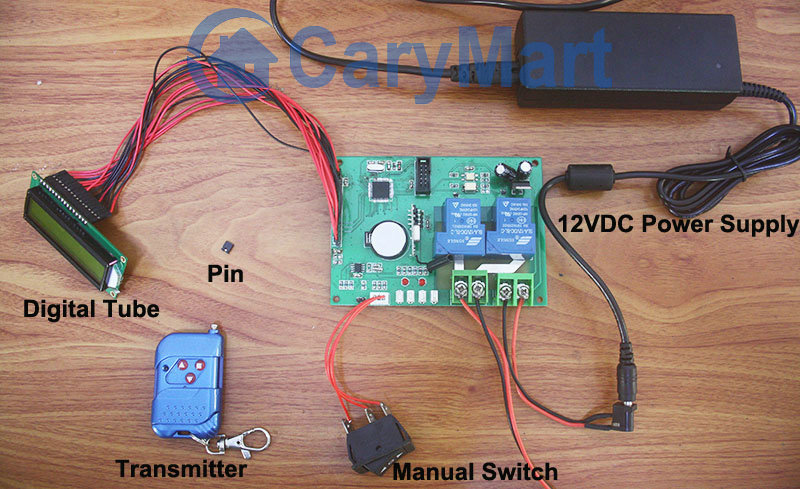
Here we talk about using the manual switch and transmitter to control motor.
Manual switch controlling:
Control positive, reverse rotation and stop of motor.
Working method: Move to “positive rotation” position, motor rotates in positive direction; move to “Stop” position, motor stops; move to “reverse rotation” position, motor rotates in reverse direction.
Remote Control with transmitter:
Insert pin to jumper: Press and hold the “▲” button, motor rotate in positive rotation; release the “▲” button, motor stops. Press and hold the “▼” button, motor rotates in reverse direction; release the “▼” button, motor stops.
Do not insert pin to jumper: Press the “▲” button, motor rotate in positive rotation; press the “■” button, motor stops. Press the “▼” button, motor rotates in reverse direction; press the “■” button, motor stops.
Here two videos for your reference.
Manual switch controlling:
Remote Control with transmitter:
DC Motor Remote Controlling by iOS Mobile Phone Wi-Fi Controller
Wi-Fi is a popular technology that allows an electric device to access or connect to the internet wireless by radio waves. Many electric devices can use Wi-Fi, for example, personal computers, Smartphones, some digital cameras and tablet computers. Nowadays, Wi-Fi is also used widely at home, public places or industry.
So we design a brand new product, Smartphone Wi-Fi Controller, which is more convenient than any other remote control products. It will integrate with Smartphone, Wi-Fi network, controller and controlled device. It gives you perfect remote controlling experience.

It works under Wi-Fi connection. With 8-channel high-current output (30amp), you can wire at least 8 devices to it. With external antenna for longer range, the theatrical working distance is 2000M (6000ft) in the open air. Actually, we design this controller for 2 Smartphone working systems— 4.6 ~ 6.1 version iOS and 2.1 ~ 4.0 version Android systems. We will illustrate the iOS system controlling DC motor here. It must Work on the jailbroken iPhone, iPad, iPod Touch. Where there is Wi-Fi networking, there is this Wi-Fi controller. It Applied in modern agriculture field, smart home, instruments, equipment controlling. Wi-Fi remote control lights, motors, fan, electric doors / windows, aircraft, remote cars, remote toys, rolling blinds, pumps, winches, or other electrical devices with voltage AC110~240V or DC0~28V.

Here is the controlling procedure of DC motor for your information. The material is Wi-Fi controller, jailbroken iPod, DC motor and power adaptor.

Connect the motor to the output terminals of WIFI controller as the wiring diagram shown.


Switch on the power of WIFI controller. Wait until power led, ready led and link led turn on. So the Wi-Fi network is connected. After wireless network connection, press the icon of WIFI Controller software to turn it.

Set up working mode for each channel of relay. Four working modes Toggle, Momentary, Latching and Time Delay are provided.
Set up Momentary control mode: Press the “M” icon of any channel. Choose M (Toggle) control mode.

Press and hold button 1, the motor is positive rotation. Release button 1, motor stops.

Press and hold button 2, the motor is reverse rotation. Release button 2, motor stops.

Video: