DC power output wireless L mode remote control receiver with 2 relays by transmitter

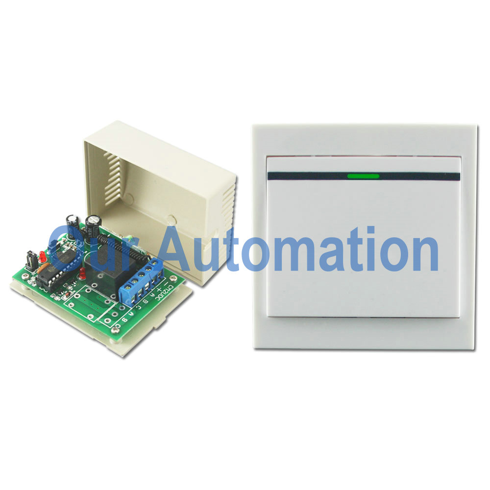
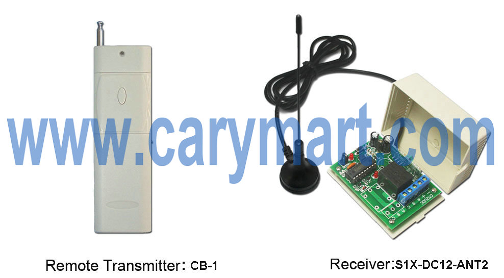
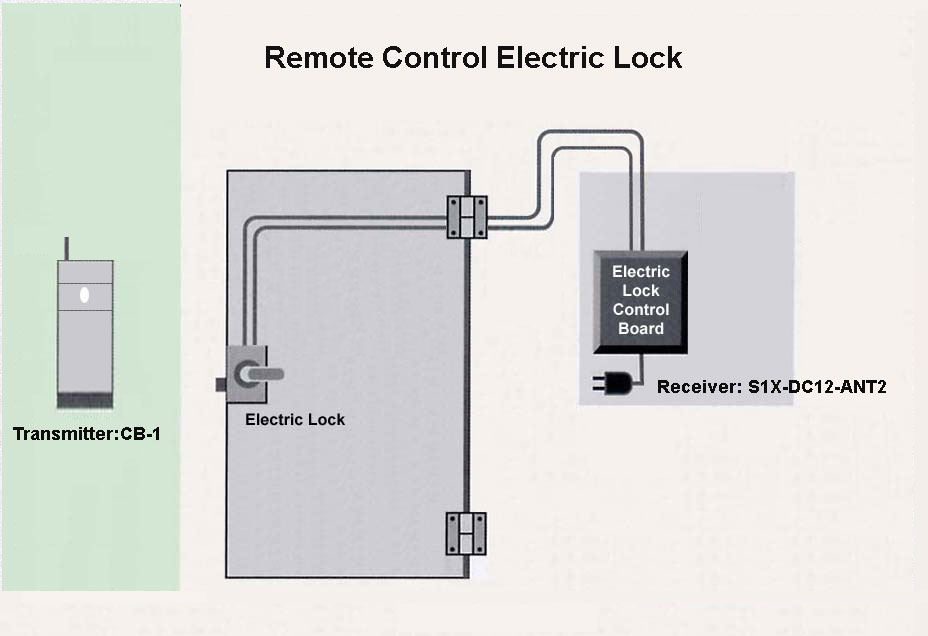
The wireless RF remote control equipment is DC power output and L control mode. It is model: S2XL-DC12 & C-3. The receiver (S2XL-DC12) is 2 CH and output power includes DC 06/09/12/24V. The transmitter remote control receiver and can work within 100m/300ft theoretically. The wireless equipment can control lights, motors, fans, electrically operated doors/locks/windows/blinds/cars or other appliances. For example, you can connect two DC motor to receiver and use the wireless transmitter remote control motor rotation or stop.

receiver & transmitter

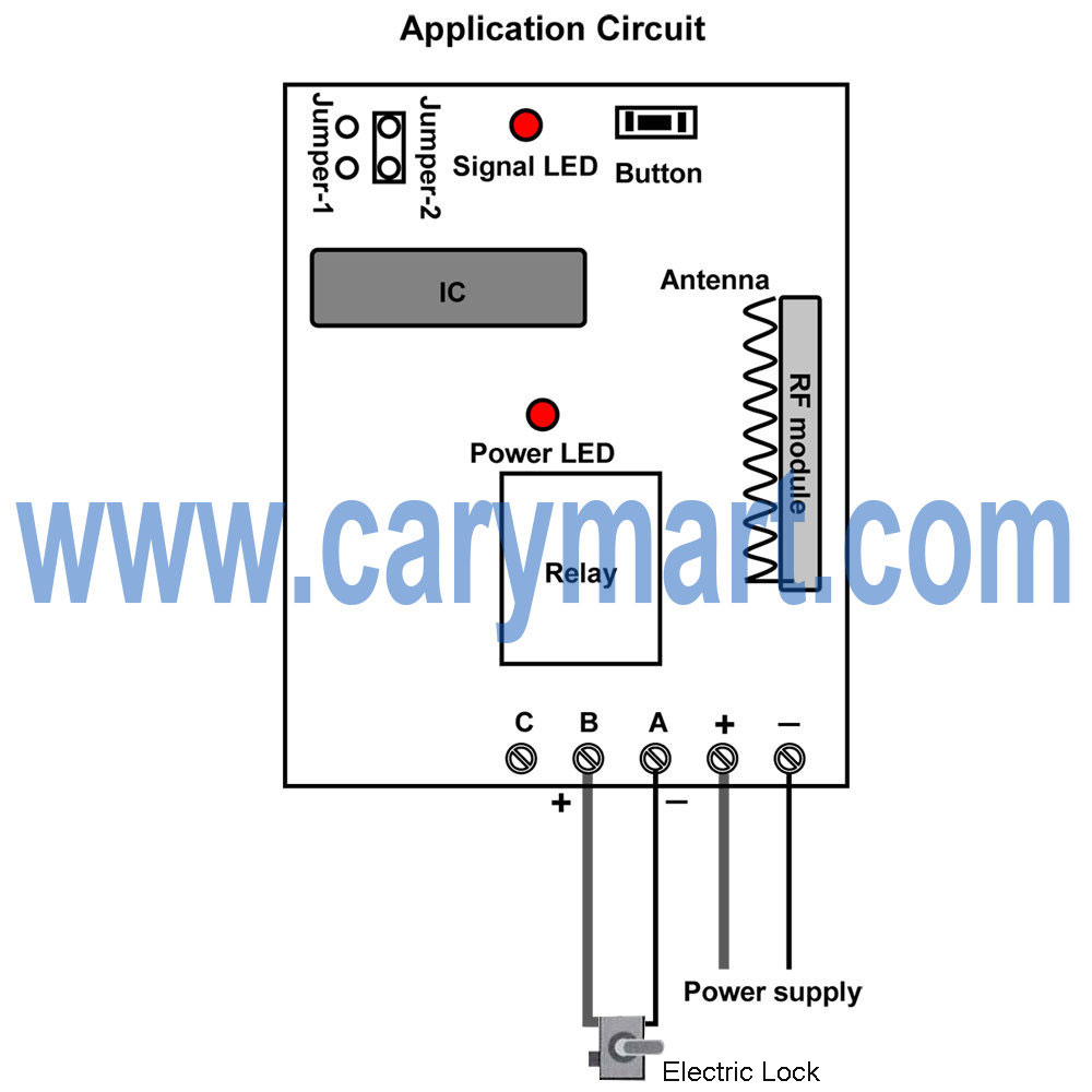
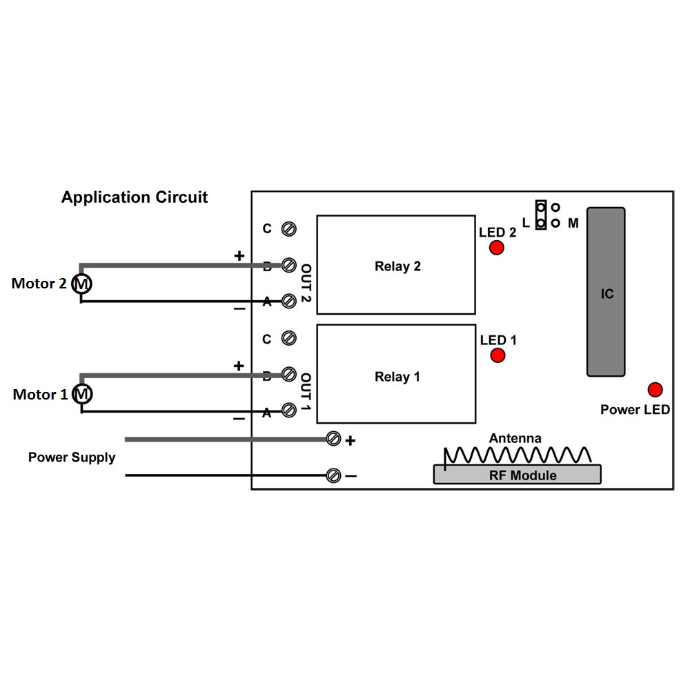
Here is the circuit diagram of receiver. You can connect motor 1 to OUT 1 terminal and motor 2 to OUT 2 terminal. After supply power to receiver, you press the button of transmitter, the motors will rotation or stop by wireless remote control.

circuit diagram

The wireless remote control equipment is L control mode. You operate as the processes:


Press button C: Turn on motor 1, terminal OUT 1 (A&B) output DC power.

Turn off motor 2, terminal OUT 2 no output.

Press button B: Turn on motor 2, terminal OUT 2 (A&B) output DC power.

Turn off motor 1, terminal OUT 1 no output.

Press button A: Turn off both motor 1 and motor 2, terminal OUT 1 and OUT2 no output.


Finally you can enter into the website and search the wireless remote control equipment as following:

Model: 0020422 (S2XL-DC12 & C-3)


Website:

http://www.carymart.com/radio-frequency-latching-remote-controller-receiver-2-function-dc-6v-9v-12v-24v-output-p-1408.html


http://www.ourautomation.com/radio-frequency-latching-remote-controller-receiver-2-function-dc-6v-9v-12v-24v-output-p-1408.html

Remote Controller is Applied to LED Lamp for Decoration

When you use led lamps to decorate your bed room, your balcony, your garden, your yard or do something glowing Christmas lighting ornament outdoor, you must be very tired with complex wiring, we try to make those wiring procedure easier.

lighting-decoration

A wireless wall-mounted switch and dc output receiver can be a new remote control unit (S1X-DC12&HR-1). It is dc power output so you can use it to control DC 0~28V actuated electrical devices off/on. This wall mounted switch is like ordinary wall switch from appearance, but it is wireless and operated by RF signal that can pass through walls, floors and doors. It is be affix to any place you want by double faced adhesive tape. The switch works with DC power output receiver, you LED lamps can wired to output terminals of receiver and also get power from them.

wall-mounted switch&receiverwall-mounted switch

Here is the wiring diagram.

Wire dc led lamp to OUTPUT of receiver. And add power supply to receiver. This kind of receiver is designed for DC output terminals so that lamp can get power from output terminals of receiver directly as mentioned above.

wiring diagram

Setting different control modes (We usually set toggle for lamp controlling.)

Setting control mode Toggle: Only connect Jumper-2.

Press button: Turn on the relay, terminal OUT outputs DC power, turn on led lamp.

Press button again: Turn off the relay, terminal OUT no output, turn off led lamp.

Remote Controller Unlocks Electric Lock

Overview:

We manage a refrigerated ice storage. We are considering an application to remotely unlock the doors using an electric strike. The application would most likely use a remote with a range of less than 150 feet typically. I am interested in getting some information about components that you might have that would work for this application.

Solution:

We recommend 1 channel 2000m dc power output receiver (S1X-DC12-ANT2) and 1-button transmitter (CB-1). Input power and output power of receiver are same as dc 12v. So it is easy for wiring. Maximum working current is 10amp. Working distance of remote and receiver set is about 2000m (6000ft) in open field. The RF signal can pass through walls, doors and other obstacles.

 remote-control-module-copy                      

Wire electric door lock and dc 12V power supply to the receiver accroding to the wiring diagram. Receiver is dc power output contact so you can connect door lock to A&B terminals. Electric door lock will get power from powered receiver.

1_06

Setting control mode Momentary: Only connect Jumper-1.

Press and hold big button: Turn on the relay, terminal A&B output DC power.

Release big button: Turn off the relay, terminal A&B no output.

When the door is locked, you can press and hold big button of the transmitter, the door will unlock.

electric-lock remote controlling set