How to Switch On and Off AC Lamp without Wiring

Question from customer:

I want switch on and off my porch light. But I don’t want do some wiring from porch to inside of my house. I want switches which can be mounted or glued to a wall. I’d like to use standard light switch fixtures as well if possible.

Can you recommend me anything that solves this situation?

Answer:

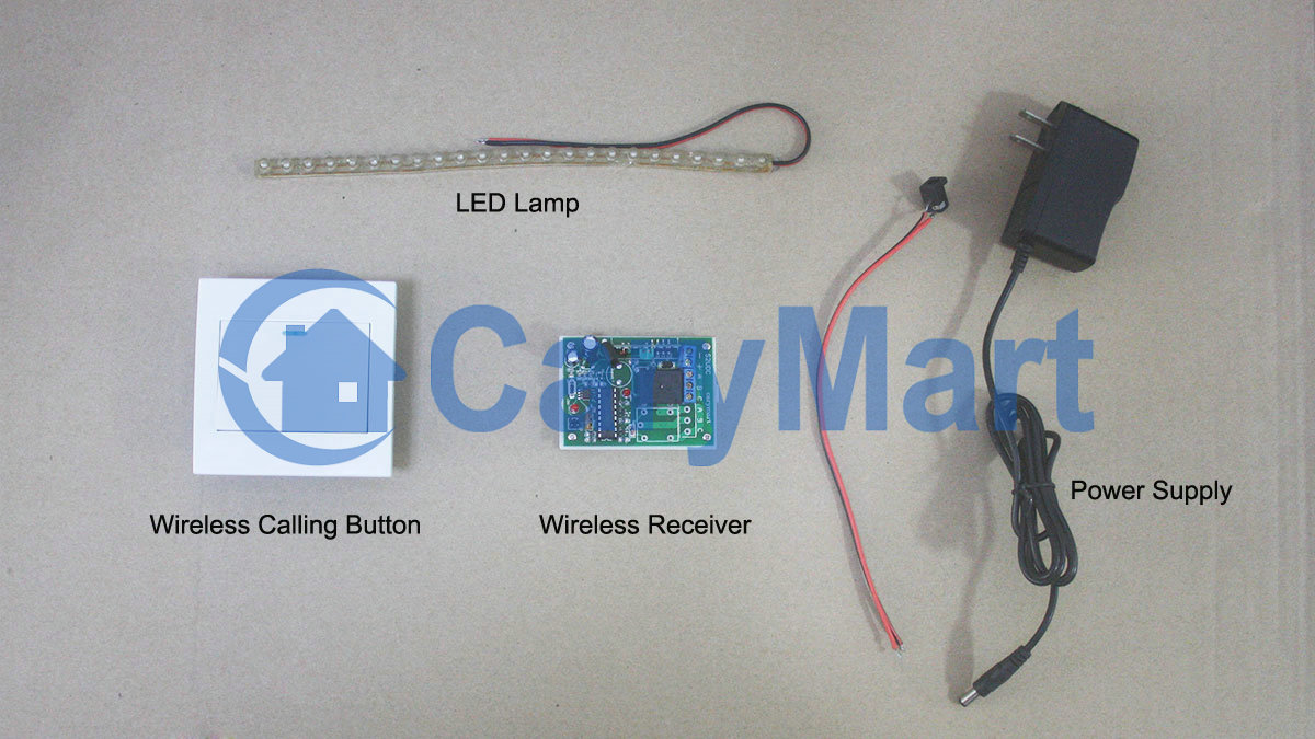
We’d like recommend this 6VDC 1 button wireless calling button with adhesive-tape and 1 channel AC220V receiver (S1X-AC220). Calling button is a part of wireless calling system, here we pair it with a wireless RF receiver to make a remote control system.

calling button&receiver

Wireless calling button is the hi-tech electronic product which is integrated wireless communication and computer technology. Usually it pair with a wireless receiver host. However, ordinary RF receiver can work with it too as long as they paired.

It is widely applied to restaurants, coffee shops, karaoke rooms, discos, sauna rooms, beer houses, pubs, night clubs, bowling alleys, golf courses, video halls, hotels, hospitals, schools, chain stores ,shops…

Wireless calling button simply stick to wall or desk by double-adhesive tape on its back. You can stick to anywhere you want. There is no need wiring from switch to lamp. Your light can be wired to the receiver and do not need supply additional power to light because it can get power from receiver.

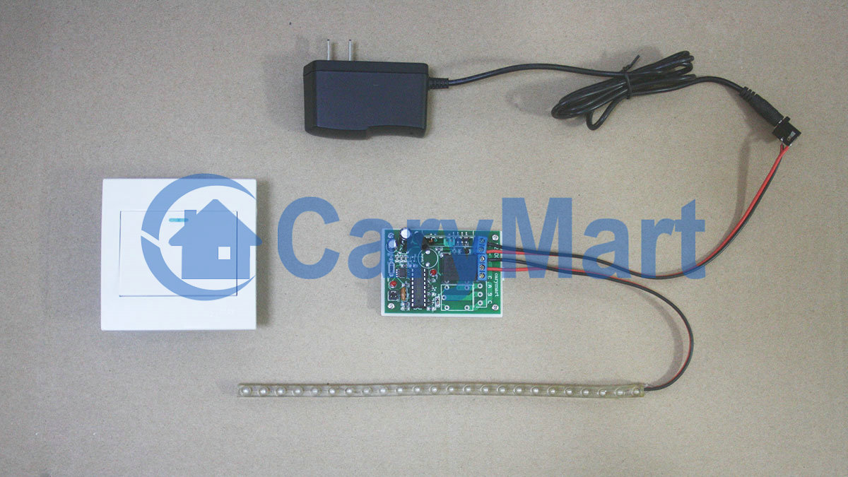
Here is the receiver wiring diagram.

1_08

S1X-AC-连走廊灯

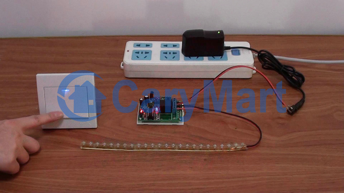
Press the “CALL” button, turn on porch lamp.

Press the “CALL” button again, turn off porch lamp.

Wall Mounting 1 Button Wireless Calling Button / Transmitter Remote Controls LED Lamp

Question from customer:

I live on a boat and have terrible access to my wiring. I really want to replace my lights and have their three switches centralized in a new location. So I have the 12v power supply to each light. I’m wondering if I can have a wireless receiver behind each light that are switched independently from three separate switches mounted on a wall. I’d like to use standard light switch fixtures as well if possible.

Can you recommend me anything that solves this situation?

Answer:

We recommend this wall mounting 1 button wireless calling button (433MHz)and 1 channel 12VDC wireless receiver (S1X-DC12). One calling button and a receiver can be paired to be a remote control kit.

calling-button&receiver

Wireless calling button is the hi-tech electronic product which is integrated wireless communication and computer technology. When there is a calling from a calling button, its paired receiver will be activated to control device which is wired to receiver.

It is widely applied to restaurants, coffee shops, karaoke rooms, discos, sauna rooms, beer houses, pubs, night clubs, bowling alleys, golf courses, video halls, hotels, hospitals, schools, chain stores ,shops…

Wireless calling button simply install to wall by screws. There is no need wiring from switch to lamp. Your light can be wired to the receiver and do not need supply additional power to light because it can get power from receiver. And you have three lights so you need three calling buttons and receivers.

We will show you the instruction.

We have wireless calling button, wireless receiver, LED lamp and power adaptor.

material

The wiring is very simple.

wiring

After switching on power, press calling button to turn on LED lamp.

lamp on

Press calling button again to turn off LED lamp.

lamp off

Video:


How Does Integrated Vibrator and Pager Work

A vibrator is a mechanical device to generate vibrations. So as components of larger product, vibrators will be widely installed in mobile phone, pagers, doorbells or other devices which need the vibrating alert. In addition, we notice another gadget-buzzer/ beeper, which is an audio signaling device. Buzzers / beepers are used in alarm device, timer and other device which needs make sound to alert. Now, we integrate two kinds of equipment with RF technology to make device- Integrated gadget with vibrator and pager (Z-06+C-1). There are three working modes for this gadget. They are vibration, beep and vibration + beep modes. It can be used in calling, animals training, alert device, reminder…

11_06

It pairs with a transmitter. We design learning code function for them. You should let receiver learn code from transmitter.

Learning code:

1) Press and hold the learning button of the receiver for about 5 seconds, then release the button when LED light is on, the receiver is in the status of Learning.

2) Press button of remote control within 10 seconds, if LED light flashes twice then off, it means Learning is successful. If LED light is off after 10 seconds, it means Learning is failed and the receiver quits the status of Learning.

3) The receiver can learn several remote controls of different codes.

Delete code:

If you don’t want the receiver to work with the remote control, you can delete all stored codes:

Delete all stored codes: Press and hold the button of the receiver for about 5 seconds until LED light turns on and go on holding till LED light turns off, then release the button, all stored codes have been deleted successfully. At this time, the transmitter cannot control the receiver.

Note:

If you want to delete all stored codes, you should first switch off the receiver and switch on again, then you can go on deleting codes.

Remote Controlling:

Vibration mode: Press the button of transmitter, the receiver vibrates for 5 seconds.

Beep mode: Press the button of transmitter, the receiver beeps for 5 seconds.

Vibration & Beep mode: Press the button of transmitter, the receiver vibrates and beeps together for 5 seconds.

Changing modes: As long as press the button of receiver, you can switch those three working modes optionally. Such as press the button of receiver, switch to beep mode from vibration mode; press the button of transmitter again, switch to vibration & beep mode; press the button of transmitter again, switch to vibration mode.

Video:

DC Motor Rotation Automation

We have set and saved the following data previously:

15:10  Motor rotates in positive direction. (The first operation), that is (W:3  C:1  R:+ WORK).

15:11  Motor stops. (The second operation), that is(W:3  C:2  R:0 WORK).

15:12  Motor rotates in reverse direction.(The third operation), that is (W:3  C:3  R:- WORK).

15:13  Motor stops. (The fourth operation), that is(W:3  C:4  R:0 WORK).

Everything is done. DC motor is ready to work when time is up.


When the real time is 15:10, motor rotates in positive direction. At the bottom of the tube screen, it displays the next operation at this time.

W:3 (Wednesday)  C:2 (The second operation)  R:0(stop) WORK

When the electronic clock reads 15:11, motor will stop.

positive-rotation

When the real time is 15:11, motor stops. At the bottom of the tube screen, it displays the next operation at this time.

W:3 (Wednesday)  C:3 (The third operation)  R:- (reverse direction) WORK

When the electronic clock reads 15:12, motor will rotate in reverse direction.

stop 1

When the real time is 15:12, motor rotates in positive direction. At the bottom of the screen, it displays the next operation at this time.

W:3 (Wednesday)  C:4 (The fourth operation)  R:0(stop) WORK

When the electronic clock reads 15:13, motor will stop.

reverse-rotation

When the real time is 15:13, motor stops. All operations are finished successfully.

stop 2

Vdieo:

Motor Automation Time Setting

We’d like to do time setting of motor rotation and stop automatically. We still use button S1~S3 to set or adjust time.

Suppose that the real time is February, 19th 2014, 15:00, Wednesday.

We will set the following data:

15:10, Wednesday, motor rotates in positive direction

15:11, Wednesday, motor stops

15:12, Wednesday, motor rotates in reverse direction

15:13 Wednesday, motor stops

Procedure:

Press and hold S1 (about 2 seconds) to enter into automatic working setting.

Press S1 again to set “Week (W)”, press S2/S3 to set W:3;

Press S1 again to set “Working times (C)”, press S2/S3 to set C:1(The first working time), C:2 (The second working time)…;

Press S1 again to set “Motor working status (R)”, press S2/S3 to set R+ /- / 0 (+ : motor positive rotation, -: motor reverse rotation, 0: motor ‘s stop)

Press S1 again to set “Motor working time”, press S2/S3 to set time of motor working status (e.g.15:10)

Press and hold S1 about 2 seconds to finish this setting and saving data.

(When you press S2/S3 to adjust data, the corresponding figure will flicker)


Finishing and saving the first setting data(15:10, Wed, Positive rotation) :

The screen reads “2014-02-19  15:02  W:3  C:1  R:+ Work”

(15:02 is the real time; W:3 is Wednesday;  C:1 is the first working time; R:+ is positive rotation)

positive rotation

Finishing and saving the second setting data(15:11, Wed, Stop):

The screen reads “2014-02-19  15:02  W:3  C:2  R:0 Work”

(15:02 is the real time; W:3 is Wednesday;  C:2 is the second working time; R:0 is motor’s  stop)

stop 1

Finishing and saving the third setting data(15:12, Wed, Reverse rotation):

The screen reads “2014-02-19  15:03  W:3  C:3  R:- Work”

(15:03 is the real time; W:3 is Wednesday;  C:3 is the third working time; R:- is reverse rotation)

reverse rotation

Finishing and saving the fourth setting data(15:13, Wed, Stop):

The screen reads “2014-02-19  15:04  W:3  C:4  R:0 Work”

(15:04 is the real time; W:3 is Wednesday;  C:4 is the fourth working time; R:0 is motor’s stop)

stop 2

Video: