Built-in Clock of Digital Tube Circuit Board Time Setting(Video)

It can be used in various fields. Working distance is about 100m.

This is circuit board can be a reversing controller, with forward-reverse-stop capability. You can rotate the motor in positive or reversal direction with the transmitter (remote control) from any place within a reliable distance and wireless RF signal can pass through walls, floors and doors. It can be controlled by maunal switch or transmitter. But now only DC power is available. It is suitable for the DC motors of blind, rolling door, projection screen, awning, winch or other appliances and mechanicals.

digital tube circuit board

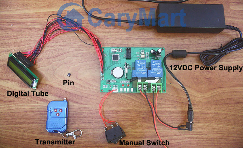
The remarkable characteristic is “Time Remote Control”, if you preset working and stop time for device and time is up, the being controlled device will work and stop according to your setting.

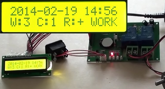
Suppose that the real time of setting is 14:56, February, 19th 2014, Wednesday.

Press S1, controller enters into the status of “date and time setting”.

Press S1 again to set “Year” to “2014”.

Press S1 again to set “Month” to “02”.

Press S1 again to set “Date” to ”19”.

Press S1 again to set “Hour” to “14”.

Press S1 again to set “Minute” to ”56”.

Press S1 again to set “Week” to” 3”.

The correspondent data will flash when we are setting. Then, press S2(+) or S3(-) to adjust according to your need. Press S1 again to save data and log out automatically when week setting is finished. After setting, we can see the following picture. The LED digital tube will read those data.

inner clock setting

Video:

Manual Switch and Transmitter of Digital Tube Circuit with Timed Controlling Function Control Motor

Digital tube circuit controller is 12VDC power activated. And motor can be wired to output terminals. The receiver and controlled device can share the same power supply. You can use manual switch or transmitter to remote control motor. In addition, with timing control function, you can preset designated time and when time is up, motor will rotate or stop automatically.

digital tube circuit board

Here we talk about using the manual switch and transmitter to control motor.

Manual switch controlling:

Control positive, reverse rotation and stop of motor.

Working method: Move to “positive rotation” position, motor rotates in positive direction; move to “Stop” position, motor stops; move to “reverse rotation” position, motor rotates in reverse direction.

Remote Control with transmitter:

Insert pin to jumper: Press and hold the “▲” button, motor rotate in positive rotation; release the “▲” button, motor stops. Press and hold the “▼” button, motor rotates in reverse direction; release the “▼” button, motor stops.

Do not insert pin to jumper: Press the “▲” button, motor rotate in positive rotation; press the “■” button, motor stops. Press the “▼” button, motor rotates in reverse direction; press the “■” button, motor stops.

Here two videos for your reference.

Manual switch controlling:

Remote Control with transmitter:

4 Channel 12VDC Remote Control Kit for Lights

Question from customer:

I need a four channel receiver and transmitter to control lights or LEDs at 300 meters, 12 volt DC power. Do you have a system? Please respond as soon as possible. Large quantities are possible if we can find the right controlling system.

Answer:

4 channel 12VDC Power Output Switch Kit (S4X-DC12-ANT2&CB-4L) is your better choice. 4 lights or LED lamps can be wired to its channels. And 4 lamps can get power directly from the powered receiver. It is very convenient to you because you don’t have to supply additional power to lights. 2000m can be reached in the open field with the external extend magnetic antenna. Besides controlling lights, it can be applied to many fields, such as motors, fans, electrically operated doors / locks / windows / blinds / cars or other appliances.

1

Here is the wiring diagram. It is simple to wire lights. Wire four lights to A&B terminals from relay 1 to relay 4. Supply 12VDC to the receiver.

1_06

There are four working modes in this kit. They are toggle, momentary, latched, momentary + toggle modes.

Setting different control modes

•1) Setting control mode Toggle: Only connect Jumper-2.

Press button A: Turn on the relay 1, terminal OUT 1 (A&B) outputs DC power.

Press button A again: Turn off the relay 1, terminal OUT 1 no output.

Press button B: Turn on the relay 2, terminal OUT 2 (A&B) outputs DC power.

Press button B again: Turn off the relay 2, terminal OUT 2 no output.

……

•2) Setting control mode Momentary: Only connect Jumper-1.

Press and hold button A: Turn on the relay 1, terminal OUT 1 (A&B) outputs DC power.

Release button A: Turn off the relay 1, terminal OUT 1 no output.

Press and hold button B: Turn on the relay 2, terminal OUT 2 (A&B) outputs DC power.

Release button B: Turn off the relay 2, terminal OUT 2 no output.

……

•3) Setting control mode Latched: Do not connect Jumper-1 and Jumper-2.

Press button A: Turn on the relay 1, terminal OUT 1 (A&B) outputs DC power.

Turn off the relay 2, terminal OUT 2 no output.

Press button B: Turn on the relay 2, terminal OUT 2 (A&B) outputs DC power.

Turn off the relay 1, terminal OUT 1 no output.

……

•4) Setting control mode Momentary (Channel 1~2) + Toggle (Channel 3~4): Connect Jumper-1 and Jumper-2.

Motor Remote Controller and Contactor Remote Control Winch

Question from customer:

Hi, I am looking for a 110 volt remote control for a winch that pulls my boat from the water into my boat house.

Requirements:

120 volt

20 amps max

Momentary switches

Do you have a kit that meets these requirements?

Boat Electric Winch

Answer:

First, we’d like to recommend motor momentary remote controller (S1FM-AC220&CV-2-2). It can remote control motors of rolling blinds/ doors, projection screens, awnings, pumps, winches, conveyors or other electric appliances and machineries. With 2 directive buttons ▲(Positive rotation) and ▼(Reversal rotation), you can rotate the motor in the positive or reversal direction with the transmitter (remote control) from any place within a reliable distance(this kind of remote controller is 500m/1500ft). Power supply is AC 100~240V. But this maximum current is 10amps, it is not enough for you to remote control your 20amps winch. So we’d like show you contactor motor starter relay, you can use it amplify current which you need. AC contactor (aka motor starter) is a high capacity relay. It is often used to control a motor or as a main power switch. It’s used for long range connection and circuit disconnection, frequent activation and controlling AC motor.

11_04

Here is the wiring diagram. Two contactors will act as a bridge between remote controller and high power motor to help activate high power motor to rotate in positive and reversal position.

connection diagram

Wire A1 terminal of contactor 1 to UP terminal of receiver, and A1 terminal of contactor 2 to DOWN of receiver. Wire T2 terminals of contactors 1&2 to winch motor. Wire winch motor to COM terminal of receiver. Supply power to receiver and contactor 1&2 respectively.

Operation:

Press and hold button ▲ on remote: Motor rotates continuously in positive direction.

Release button ▲ on remote: Stop the motor.

Press and hold button ▼ on remote: Motor rotates continuously in reversal direction.

Release button▼ on remote: Stop the motor.