Remote Control Car Backup Camera

Overview:

I would like to turn on/off the wireless reversing camera on my car (12V). What device can you recommend?

car-reversing-camera

Solution:

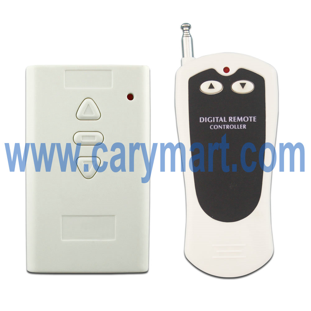
We recommend this 1 channel 12V universal remote control model (S1U-DC12-ANT1+C-2).

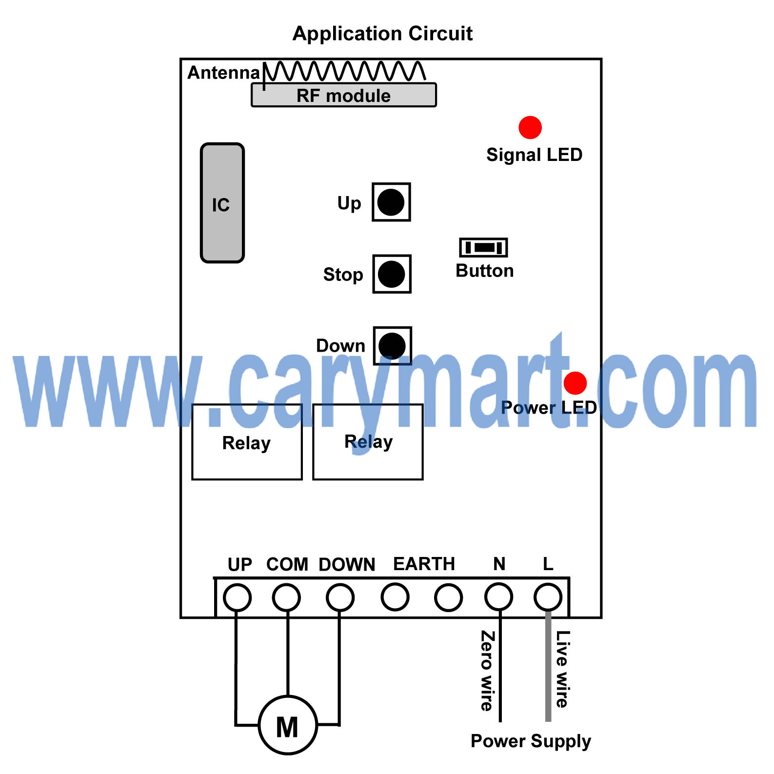
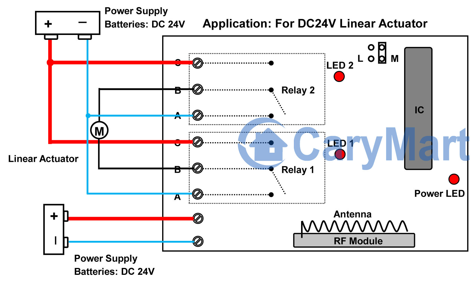
You can wire reversing camera power lines to normally open terminals B&C of receiver. Receiver and reversing camera can share the same power supply (12V) together.

wiring-diagram

This 1CH rf remote control switch operates in toggle, momentary and latched control mode (set the mode as you like freely). And you’d better choose toggle mode or latched mode. It is great for hard to reach lights or other DC/AC electrical devices. With external telescopic antenna, the receiver has farther working range (about 100m).

1_02

Operation:

Setting control mode Toggle: Connect Jumper-2.

Control mode Toggle: Press -> On; Press again -> Off.

Press button 1: Turn on the reversing camera (connect B and C, disconnect A and B)

Press button 1 again: Turn off the reversing camera (disconnect B and C, connect A and B)


Setting control mode Latched: Disconnect Jumper-1 and Jumper-2.

Control mode Latched: Press -> On, other relays Off; Press another button -> Off.

Press button 1: Turn on the reversing camera (connect B and C, disconnect A and B)

Press button 2: Turn off the reversing camera (disconnect B and C, connect A and B)

1 Channel Momentary Controller Control Hydraulic Lift Up and Down

The hydraulic lift is a device used to lift or bring down loads from one floor to another in multi-storeyed buildings or stereo garage car lifting. The hydraulic lifts are used widely in cars, containers, mold making, timber processing and chemical filling for purpose of different working height need. Maybe you just want to use small-sized hydraulic lift platform to do something and just want it to be remote controlled so that it can bring you more convenience.

hydraulic lift

Here you can use 1 channel momentary controller (S1FM-AC220+CV-2-2) to remote control your hydraulic lift up and down.

This kind of controller has inversion control mode. It is 10 amps of its maximum current and 500m working distance. The operation is also very easy.

1_01

Connect live wire to terminal “L” and neutral wire to terminal “N”. Then connect AC motor to terminals “UP”, “COMMON” and “DOWN”. You can exchange “UP” and “DOWN” wires of motor to change the rotating direction of motor.

1_06

Press and hold button ▲ on remote or receiver: Terminals UP and COMMON directly output AC110V / AC220V; motor rotates continuously in positive direction.

Release button ▲ on remote or receiver: Stop the motor.

Press and hold button ▼ on remote or receiver: Terminals DOWN and COMMON directly output AC110V / AC220V; motor rotates continuously in reversal direction.

Release button ▼ on remote or receiver: Stop the motor.

How to Remote Control Linear Motion Actuator Run Forward and Backward

Question from customer:

I have 24V Linear Motion Actuator which moves 2 ways (OUT and IN). Also I have 24V power Supply.

I would like to connect the remote control, and be able to open and close the actuator. Ideally, I want to press the button until actuator extends fully, and press another button to retract fully.

Linear Actuator

Answer:

We recommend this 2 channel wireless remote control momentary on off switch which is widely applied to lights, motors, fans, electrically operated doors / locks / windows / blinds, etc. One relay as an ON/OFF switch can turn on or off electric gadget. If you want to remote control  bidirectional motion, you may choose 2 channel remote (two relays). Your linear motion actuator can run forward and backward, so this remote is very available for you. It provides linear motion actuator with 10A. It is enough for linear motion actuator. With 2-button transmitter, its working distance reaches about 100m which can make your control range much wider, getting rid of narrow space constraint.

1

The wiring of linear motion actuator is a little sophisticated. See the following picture.

motor circuit

Initial state: A, B = Normally Closed; B, C = Normally Open.

So wire linear motion actuator to B terminals of two relays. Wire “C” terminals of two relays together to positive electrode of 24 batteries. Wire “A” terminals of two relays together to negative electrode of 24 batteries. And supply additional power to the receiver. It can avoid generating interfere between receiver and linear motion actuator.

Momentary mode is the only working mode in this remote. So press and hold button 1, linear motion actuator extends slowly, if you release button 1, it stops moving. Press and hold button 2, linear motion actuator retracts slowly, if you release button 2, it stops moving.

How to Remote Control 240V 25 amps Electric Equipment

Question from customer:

I am looking for an RF switch and transmitter where the switch has a coil voltage up to 12v and the switch terminal can handle 240v and 25 amps. Do you have anything like this?

Answer:

We recommend 1 channel high power remote controller (S1PU-DC12&C-2). The receiver is normally open and closed contact, so you can wire the gadget which is activated by AC 110~240V or DC0~28V.  The relay outputs 30amps current for gadget. It meets your needs. The receiver is run by 12VDC, but receiver and controller gadget will be supplied power separately so that they won’t interfere to each other. The transmitter is 2-button type remote. When it works with receiver together, their working distances reach 100m.

1_02

Here is the sample of wiring method.

Suppose that we remote control a lamp. The normally open terminals are A&B. The normally open terminals are A&C. Lamp should be connected to A&C terminals. Normally open and closed contact is similar with an ON/OFF switch. The being controlled gadget cannot get power from powered receiver. We should supply additional power to it. We can supply DC or AC power to controlled gadget according to its available power supply.

1_09

Toggle mode, momentary mode and latched mode are its working modes.

Setting control mode Toggle: Only connect Jumper-1.

Control mode Toggle: Press -> On; Press again -> Off.

Press button 1: Turn on the gadget

Press button 1 again: Turn off the gadget

Setting control mode Momentary: Only connect Jumper-2.

Control mode Momentary: Press and hold -> On; Release -> Off.

Press and hold button 1: Turn on the gadget

Release button 1: Turn off the gadget

Setting control mode Latched: Disconnect Jumper-1 and Jumper-2.

Control mode Latched: Press -> On, other relays Off; Press another button -> Off.

Press button 1: Turn on the gadget

Press button 2: Turn off the gadget

Customized Time Delay 6V Remote Controller for Lamp

This 1 channel dc RF remote control switch features in controlling relay off time delay. Delay time can be customized according to actual requirement. It is widely applied to control lights, motors, fans, electrically operated doors / locks / windows / blinds or other electrical devices. It is activated in 6V power supply. You need provide us with the delay time you want when ordering. E.g. delay time: 20 seconds or 1 hour or 20 minutes… The delay time is not adjustable freely. Its working current is 10ampere and working distance is 100m (300ft).

1

It has normally open and closed contact. It controls various lights, fans or motors with voltage AC110~240V or DC0~28V. Here is the alternate current device wiring diagram and the wiring diagram of direct current device which not share the same power supply with receiver.

1_08

Of course, if you want to remote control direct current device which shares the same power supply with receiver, you need to do some different wiring from above wiring. Suppose that you want to remote control 6V lamp. So you don’t have to supply additional power for led lamp because led lamp will get power from powered receiver as long as you wire lamp to the receiver.

Here is the wiring procedure of 6V lamp which shares the same battery with receiver. The red wire from the lamp is connected to the C terminal of the receiver and black wire from the lamp is connected to the negative electrode of the power supply. The positive wire of the supply power is connected to B terminal and positive electrode of the receiver. The negative electrode of the power supply of power supply and receiver are connected together.

circuit

We set its delay time 20seconds.

Press button 1: Turn on the lamp. After 20seconds, turn off the lamp by itself.

During the delay time, press button 2: Turn off the lamp straightway.