Motor Automation Time Setting

We’d like to do time setting of motor rotation and stop automatically. We still use button S1~S3 to set or adjust time.

Suppose that the real time is February, 19th 2014, 15:00, Wednesday.

We will set the following data:

15:10, Wednesday, motor rotates in positive direction

15:11, Wednesday, motor stops

15:12, Wednesday, motor rotates in reverse direction

15:13 Wednesday, motor stops

Procedure:

Press and hold S1 (about 2 seconds) to enter into automatic working setting.

Press S1 again to set “Week (W)”, press S2/S3 to set W:3;

Press S1 again to set “Working times (C)”, press S2/S3 to set C:1(The first working time), C:2 (The second working time)…;

Press S1 again to set “Motor working status (R)”, press S2/S3 to set R+ /- / 0 (+ : motor positive rotation, -: motor reverse rotation, 0: motor ‘s stop)

Press S1 again to set “Motor working time”, press S2/S3 to set time of motor working status (e.g.15:10)

Press and hold S1 about 2 seconds to finish this setting and saving data.

(When you press S2/S3 to adjust data, the corresponding figure will flicker)


Finishing and saving the first setting data(15:10, Wed, Positive rotation) :

The screen reads “2014-02-19  15:02  W:3  C:1  R:+ Work”

(15:02 is the real time; W:3 is Wednesday;  C:1 is the first working time; R:+ is positive rotation)

positive rotation

Finishing and saving the second setting data(15:11, Wed, Stop):

The screen reads “2014-02-19  15:02  W:3  C:2  R:0 Work”

(15:02 is the real time; W:3 is Wednesday;  C:2 is the second working time; R:0 is motor’s  stop)

stop 1

Finishing and saving the third setting data(15:12, Wed, Reverse rotation):

The screen reads “2014-02-19  15:03  W:3  C:3  R:- Work”

(15:03 is the real time; W:3 is Wednesday;  C:3 is the third working time; R:- is reverse rotation)

reverse rotation

Finishing and saving the fourth setting data(15:13, Wed, Stop):

The screen reads “2014-02-19  15:04  W:3  C:4  R:0 Work”

(15:04 is the real time; W:3 is Wednesday;  C:4 is the fourth working time; R:0 is motor’s stop)

stop 2

Video:

Manual Switch and Transmitter of Digital Tube Circuit with Timed Controlling Function Control Motor

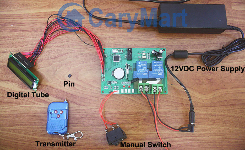
Digital tube circuit controller is 12VDC power activated. And motor can be wired to output terminals. The receiver and controlled device can share the same power supply. You can use manual switch or transmitter to remote control motor. In addition, with timing control function, you can preset designated time and when time is up, motor will rotate or stop automatically.

digital tube circuit board

Here we talk about using the manual switch and transmitter to control motor.

Manual switch controlling:

Control positive, reverse rotation and stop of motor.

Working method: Move to “positive rotation” position, motor rotates in positive direction; move to “Stop” position, motor stops; move to “reverse rotation” position, motor rotates in reverse direction.

Remote Control with transmitter:

Insert pin to jumper: Press and hold the “▲” button, motor rotate in positive rotation; release the “▲” button, motor stops. Press and hold the “▼” button, motor rotates in reverse direction; release the “▼” button, motor stops.

Do not insert pin to jumper: Press the “▲” button, motor rotate in positive rotation; press the “■” button, motor stops. Press the “▼” button, motor rotates in reverse direction; press the “■” button, motor stops.

Here two videos for your reference.

Manual switch controlling:

Remote Control with transmitter:

30amps 100M Remote Controller for Submersible Pump

Question from customer:

I am in Australia and here we have Live-Re and Neutral-Black and Earth-Green. I wish to wire a submersible pump to your radio controller then back to the consumer mains. Please advise if wiring would be.

Mains :

Live Red          to            Controller  Power Supply L

Neutral Black  to           Controller Power Supply N

Controller terminal A               to  Pump Live Red

Controller terminal B                    to Pump Neutral Black

What is the terminal C in the controller used for? How is the earth cable from the pump and the incoming power cable earth to be connected via the controller?

Answer:

We recommend you 1 channel 30amps remote controller kit (S1PU-AC220&C-2). This 1 channel 30A rf remote control kit operates in toggle, momentary and latched control mode (set the mode as you like freely). It is great for hard to reach electrical devices, remote distance is 100m. Control lights, motors, fans, electrically operated doors / locks / windows / blinds / cars or other appliances with voltage AC110~240V or DC0~28V.

1

The outputs of this receiver are relay outputs (the terminals are normally open and normally closed), they are not AC power outputs. It just amount to a switch to turn on or off device.

If you want to turn on / off the pump by this product, the connections are as following:

Live Red        to       Controller  Power Supply L

Neutral Black    to       Controller  Power Supply N

Live Red        to       Controller terminal B

Neutral Black    to       Pump Neutral Black

Controller terminal A   to           Pump Live Red

the earth cable from the pump  to     Earth – Green

circuit

Usage:

Setting control mode Toggle: Only connect Jumper-2. Control mode Toggle: Press -> On; Press again -> Off. Press button 1: Turn on the  submersible pump. Press button 1 again: Turn off the  submersible pump.

Setting control mode Momentary: Only connect Jumper-1. Control mode Momentary: Press and hold -> On; Release -> Off. Press and hold button 1: Turn on the  submersible pump. Release button 1: Turn off the  submersible pump.

Setting control mode Latched: Disconnect Jumper-1 and Jumper-2. Control mode Latched: Press -> On, other relays Off; Press another button -> Off. Press button 1: Turn on the submersible pump. Press button 2: Turn off the  submersible pump.

How to Remote Control 240V 25 amps Electric Equipment

Question from customer:

I am looking for an RF switch and transmitter where the switch has a coil voltage up to 12v and the switch terminal can handle 240v and 25 amps. Do you have anything like this?

Answer:

We recommend 1 channel high power remote controller (S1PU-DC12&C-2). The receiver is normally open and closed contact, so you can wire the gadget which is activated by AC 110~240V or DC0~28V.  The relay outputs 30amps current for gadget. It meets your needs. The receiver is run by 12VDC, but receiver and controller gadget will be supplied power separately so that they won’t interfere to each other. The transmitter is 2-button type remote. When it works with receiver together, their working distances reach 100m.

1_02

Here is the sample of wiring method.

Suppose that we remote control a lamp. The normally open terminals are A&B. The normally open terminals are A&C. Lamp should be connected to A&C terminals. Normally open and closed contact is similar with an ON/OFF switch. The being controlled gadget cannot get power from powered receiver. We should supply additional power to it. We can supply DC or AC power to controlled gadget according to its available power supply.

1_09

Toggle mode, momentary mode and latched mode are its working modes.

Setting control mode Toggle: Only connect Jumper-1.

Control mode Toggle: Press -> On; Press again -> Off.

Press button 1: Turn on the gadget

Press button 1 again: Turn off the gadget

Setting control mode Momentary: Only connect Jumper-2.

Control mode Momentary: Press and hold -> On; Release -> Off.

Press and hold button 1: Turn on the gadget

Release button 1: Turn off the gadget

Setting control mode Latched: Disconnect Jumper-1 and Jumper-2.

Control mode Latched: Press -> On, other relays Off; Press another button -> Off.

Press button 1: Turn on the gadget

Press button 2: Turn off the gadget

Customized Time Delay 6V Remote Controller for Lamp

This 1 channel dc RF remote control switch features in controlling relay off time delay. Delay time can be customized according to actual requirement. It is widely applied to control lights, motors, fans, electrically operated doors / locks / windows / blinds or other electrical devices. It is activated in 6V power supply. You need provide us with the delay time you want when ordering. E.g. delay time: 20 seconds or 1 hour or 20 minutes… The delay time is not adjustable freely. Its working current is 10ampere and working distance is 100m (300ft).

1

It has normally open and closed contact. It controls various lights, fans or motors with voltage AC110~240V or DC0~28V. Here is the alternate current device wiring diagram and the wiring diagram of direct current device which not share the same power supply with receiver.

1_08

Of course, if you want to remote control direct current device which shares the same power supply with receiver, you need to do some different wiring from above wiring. Suppose that you want to remote control 6V lamp. So you don’t have to supply additional power for led lamp because led lamp will get power from powered receiver as long as you wire lamp to the receiver.

Here is the wiring procedure of 6V lamp which shares the same battery with receiver. The red wire from the lamp is connected to the C terminal of the receiver and black wire from the lamp is connected to the negative electrode of the power supply. The positive wire of the supply power is connected to B terminal and positive electrode of the receiver. The negative electrode of the power supply of power supply and receiver are connected together.

circuit

We set its delay time 20seconds.

Press button 1: Turn on the lamp. After 20seconds, turn off the lamp by itself.

During the delay time, press button 2: Turn off the lamp straightway.