1 Channel RF Remote Controller Switch AC Lamp Off/On

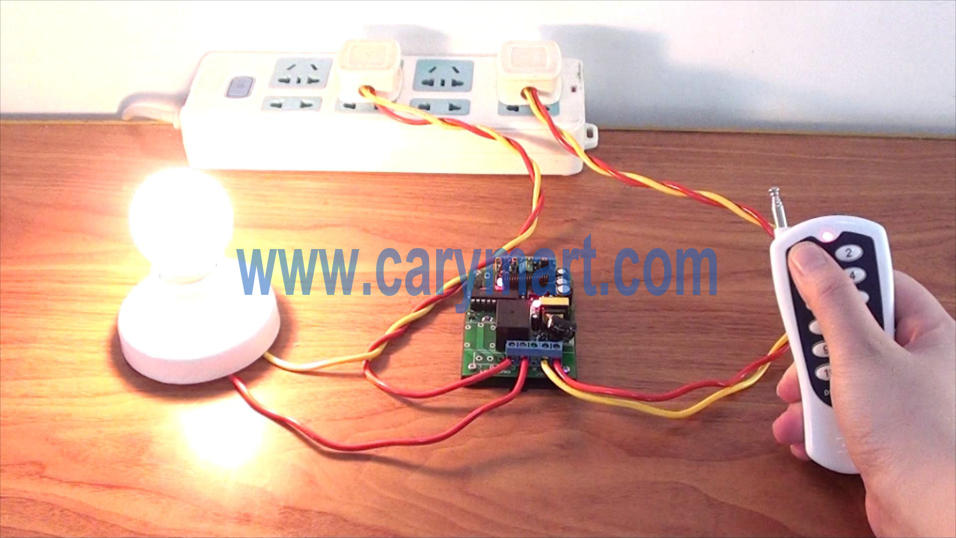
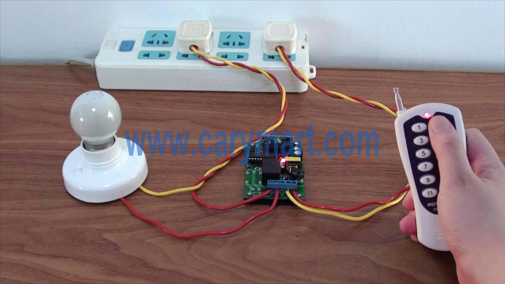
This is the one-to-many series remote controller. The 1 channel rf receiver is normally open &closed contact, you can wire lights, motors, fans, electrically operated doors / locks / windows / blinds / cars or other appliances with AC 110~240V or DC 0~28V. The transmitter is 12-button and its transmitter is 500m/1500ft. That transmitter can remote control 12 lamps at most when it pairs up with 12 receivers. Here you will see an example to remote control one ac lamp with this kind of remote controller.

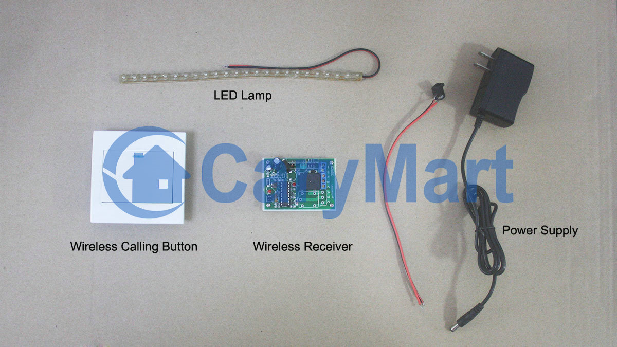
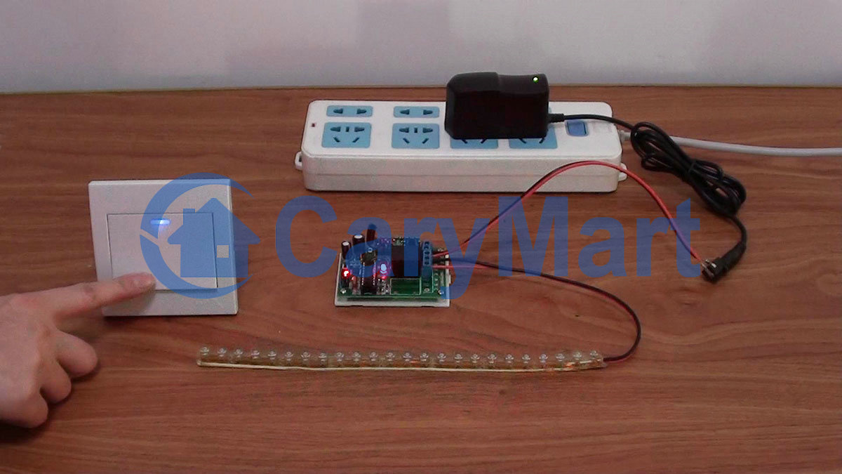
Here is the material.

material

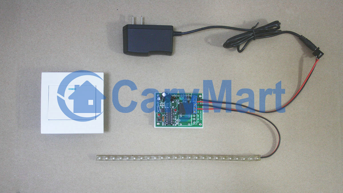
Next step is the wiring.

wiring

Setting control mode Latched: Do not connect Jumper-1 and Jumper-2

Press button 1, turn on lamp.

button 1 light on

Press other button, turn off lamp.

button 2 light off

Video

2000m 9V Actuated Toggle Mode Remote Controller Works at a Port

Overview:

I am looking for a RF Remote Control covers a distance of 1000-2000 meters for one port only, and output Relay Minimum with current 3 amps and working on the 9-volt battery.

small-port

Solution:

We recommend This 1 channel dc rf remote control system (S1T-DC09-ANT2+CB-1), which operates in 6V/9V/12V/24V. 12V is the standard voltage. 9V is also available if you need. Any device with voltage of AC110~240V or DC0~28V can be connected to that controller. It is great for hard to reach lights or other DC/AC electrical devices, remote distance is up to 2000m. Applications include light remote control, electric gate remote control, electric window / blind remote control, etc. Then maximum current output is 10 amps and it can work on the 9-volt battery. Transmitter distance is 2000m in the open field.

1

It is the normally open and closed contact, so your device at port is supposed to be wired to normally open contact. You can only wire one device on that controller because it has only one relay (one channel).

1_06

After wiring, the device at port should be added additional power. Turn on the controller.

Press button: Turn on relay, turn on device (connect B and C, disconnect A and B)

Press button again: Turn off relay, turn off device (disconnect B and C, connect A and B)

1 Channel Momentary Controller Control Hydraulic Lift Up and Down

The hydraulic lift is a device used to lift or bring down loads from one floor to another in multi-storeyed buildings or stereo garage car lifting. The hydraulic lifts are used widely in cars, containers, mold making, timber processing and chemical filling for purpose of different working height need. Maybe you just want to use small-sized hydraulic lift platform to do something and just want it to be remote controlled so that it can bring you more convenience.

hydraulic lift

Here you can use 1 channel momentary controller (S1FM-AC220+CV-2-2) to remote control your hydraulic lift up and down.

This kind of controller has inversion control mode. It is 10 amps of its maximum current and 500m working distance. The operation is also very easy.

1_01

Connect live wire to terminal “L” and neutral wire to terminal “N”. Then connect AC motor to terminals “UP”, “COMMON” and “DOWN”. You can exchange “UP” and “DOWN” wires of motor to change the rotating direction of motor.

1_06

Press and hold button ▲ on remote or receiver: Terminals UP and COMMON directly output AC110V / AC220V; motor rotates continuously in positive direction.

Release button ▲ on remote or receiver: Stop the motor.

Press and hold button ▼ on remote or receiver: Terminals DOWN and COMMON directly output AC110V / AC220V; motor rotates continuously in reversal direction.

Release button ▼ on remote or receiver: Stop the motor.

Wall Mounting 1 Button Wireless Calling Button / Transmitter Remote Controls LED Lamp

Question from customer:

I live on a boat and have terrible access to my wiring. I really want to replace my lights and have their three switches centralized in a new location. So I have the 12v power supply to each light. I’m wondering if I can have a wireless receiver behind each light that are switched independently from three separate switches mounted on a wall. I’d like to use standard light switch fixtures as well if possible.

Can you recommend me anything that solves this situation?

Answer:

We recommend this wall mounting 1 button wireless calling button (433MHz)and 1 channel 12VDC wireless receiver (S1X-DC12). One calling button and a receiver can be paired to be a remote control kit.

calling-button&receiver

Wireless calling button is the hi-tech electronic product which is integrated wireless communication and computer technology. When there is a calling from a calling button, its paired receiver will be activated to control device which is wired to receiver.

It is widely applied to restaurants, coffee shops, karaoke rooms, discos, sauna rooms, beer houses, pubs, night clubs, bowling alleys, golf courses, video halls, hotels, hospitals, schools, chain stores ,shops…

Wireless calling button simply install to wall by screws. There is no need wiring from switch to lamp. Your light can be wired to the receiver and do not need supply additional power to light because it can get power from receiver. And you have three lights so you need three calling buttons and receivers.

We will show you the instruction.

We have wireless calling button, wireless receiver, LED lamp and power adaptor.

material

The wiring is very simple.

wiring

After switching on power, press calling button to turn on LED lamp.

lamp on

Press calling button again to turn off LED lamp.

lamp off

Video:


DC Motor Rotation Automation

We have set and saved the following data previously:

15:10  Motor rotates in positive direction. (The first operation), that is (W:3  C:1  R:+ WORK).

15:11  Motor stops. (The second operation), that is(W:3  C:2  R:0 WORK).

15:12  Motor rotates in reverse direction.(The third operation), that is (W:3  C:3  R:- WORK).

15:13  Motor stops. (The fourth operation), that is(W:3  C:4  R:0 WORK).

Everything is done. DC motor is ready to work when time is up.


When the real time is 15:10, motor rotates in positive direction. At the bottom of the tube screen, it displays the next operation at this time.

W:3 (Wednesday)  C:2 (The second operation)  R:0(stop) WORK

When the electronic clock reads 15:11, motor will stop.

positive-rotation

When the real time is 15:11, motor stops. At the bottom of the tube screen, it displays the next operation at this time.

W:3 (Wednesday)  C:3 (The third operation)  R:- (reverse direction) WORK

When the electronic clock reads 15:12, motor will rotate in reverse direction.

stop 1

When the real time is 15:12, motor rotates in positive direction. At the bottom of the screen, it displays the next operation at this time.

W:3 (Wednesday)  C:4 (The fourth operation)  R:0(stop) WORK

When the electronic clock reads 15:13, motor will stop.

reverse-rotation

When the real time is 15:13, motor stops. All operations are finished successfully.

stop 2

Vdieo: