Question from customer:
He was looking for the RF wireless remote control that includes a two button transmitter & two channel receiver. When push one button on the remote, the dry contacts are closed; if release the button, the dry contacts are open. The second button must work on the same way. Controlling two electric appliances simultaneously is also his requirement. He can provide 220 V AC supply power.
Answer:
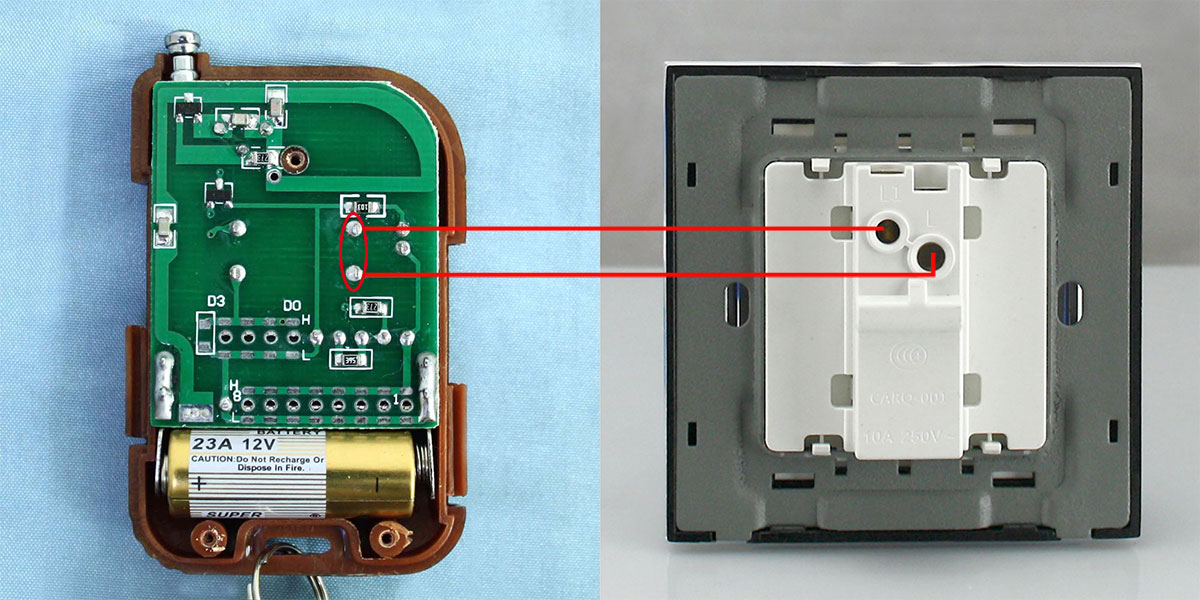
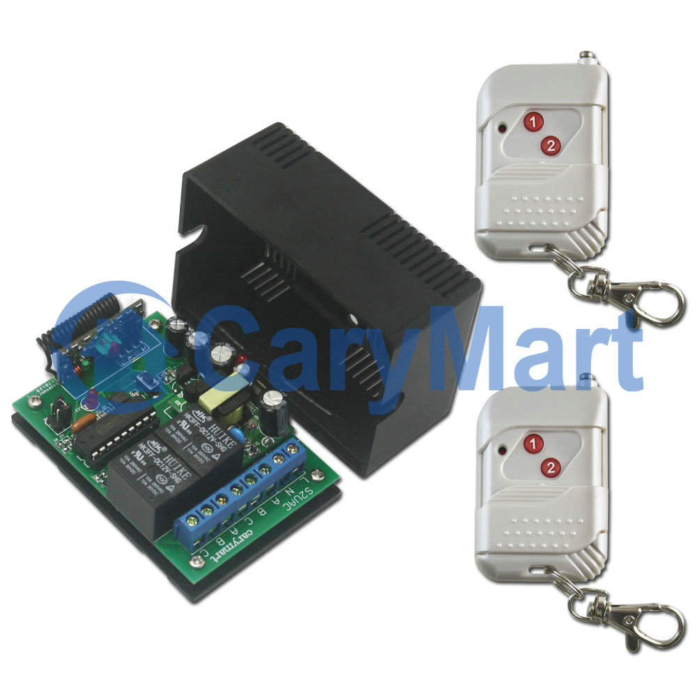
After we take these questions into consideration, Model 0020333 (S2U-AC220 & C-2) is the best suitable .The RF wireless remote control consists of the receiver (S2U- AC220 ) and the transmitter ( C-2). There are two relays which work by dry contacts on / off in the receiver. This is to say, when you press button 1 on the transmitter (remote control), the first dry contact is closed and one electric appliance turns on ; if you release button 1, the dry contacts are open and the two electric appliances turn off. The button 2 on the transmitter remotely control the other electric appliance in the same way.
We should supply additional 220V AC power to the receiver in order that the receiver can work. The transmitter (remote control) is no wire, so it is convenient for you to carry it . You can turn on/off the receiver with transmitter from any place within a reliable distance; the wireless RF signal can pass through walls, floors and doors. The reliable distance of the remote control can reach up to 100m/300ft theoretically. Two buttons can control two electric appliances respectively. For example, we wire two lamps to the output terminals of the relays; when you press button 1, lamb 1 turns on; if the button 1 is released, lamb 1 turns off. Button 2 remotely controls lamb 2 in the same way.
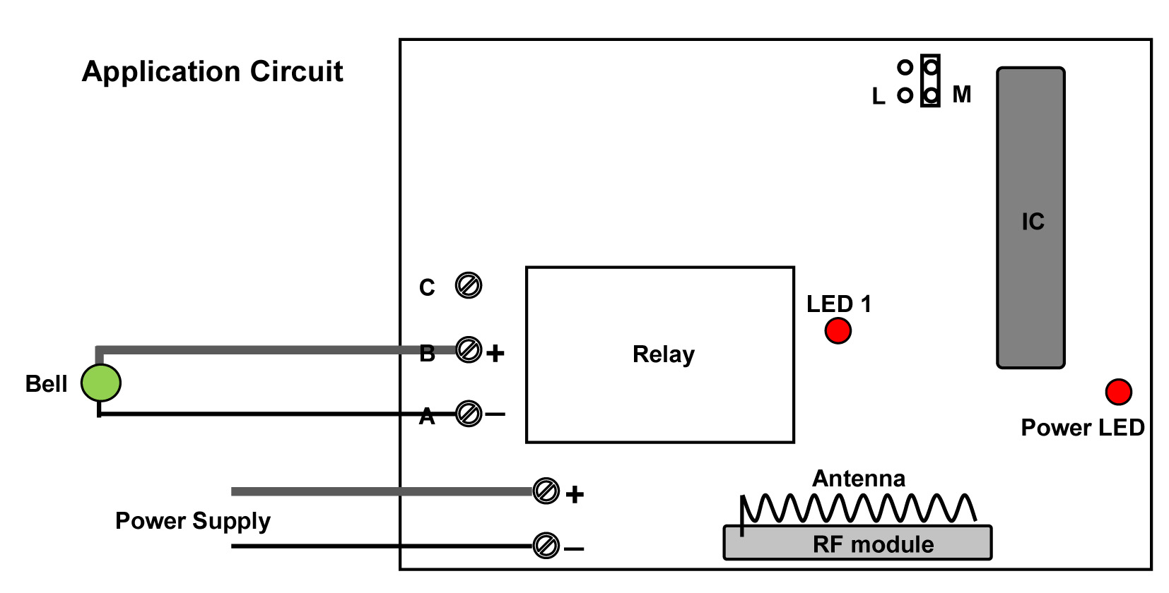
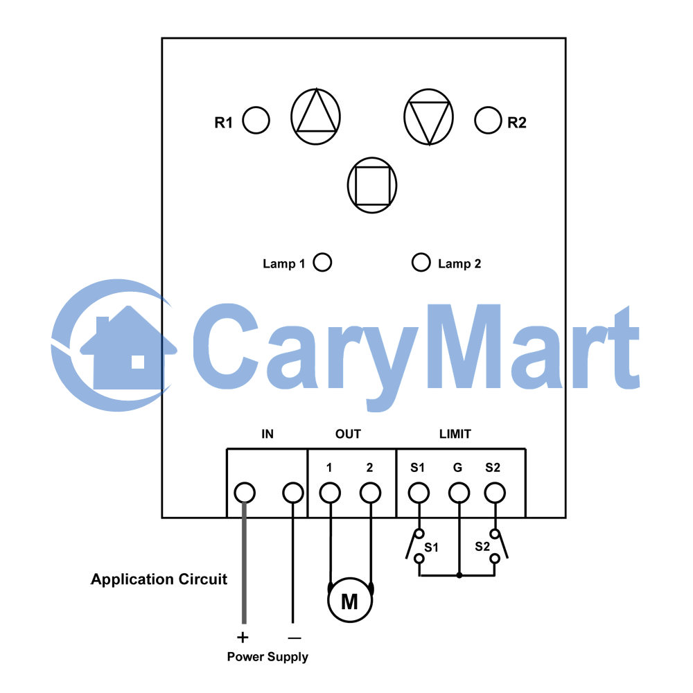
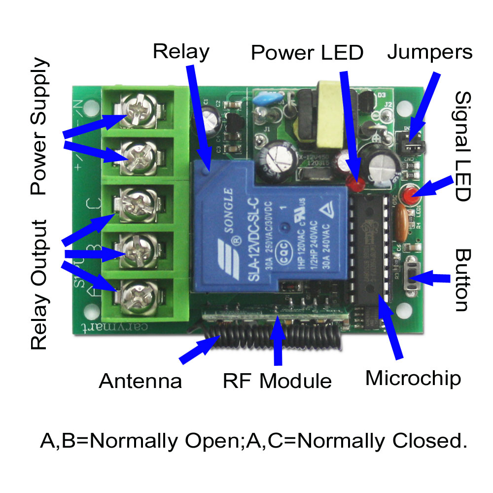
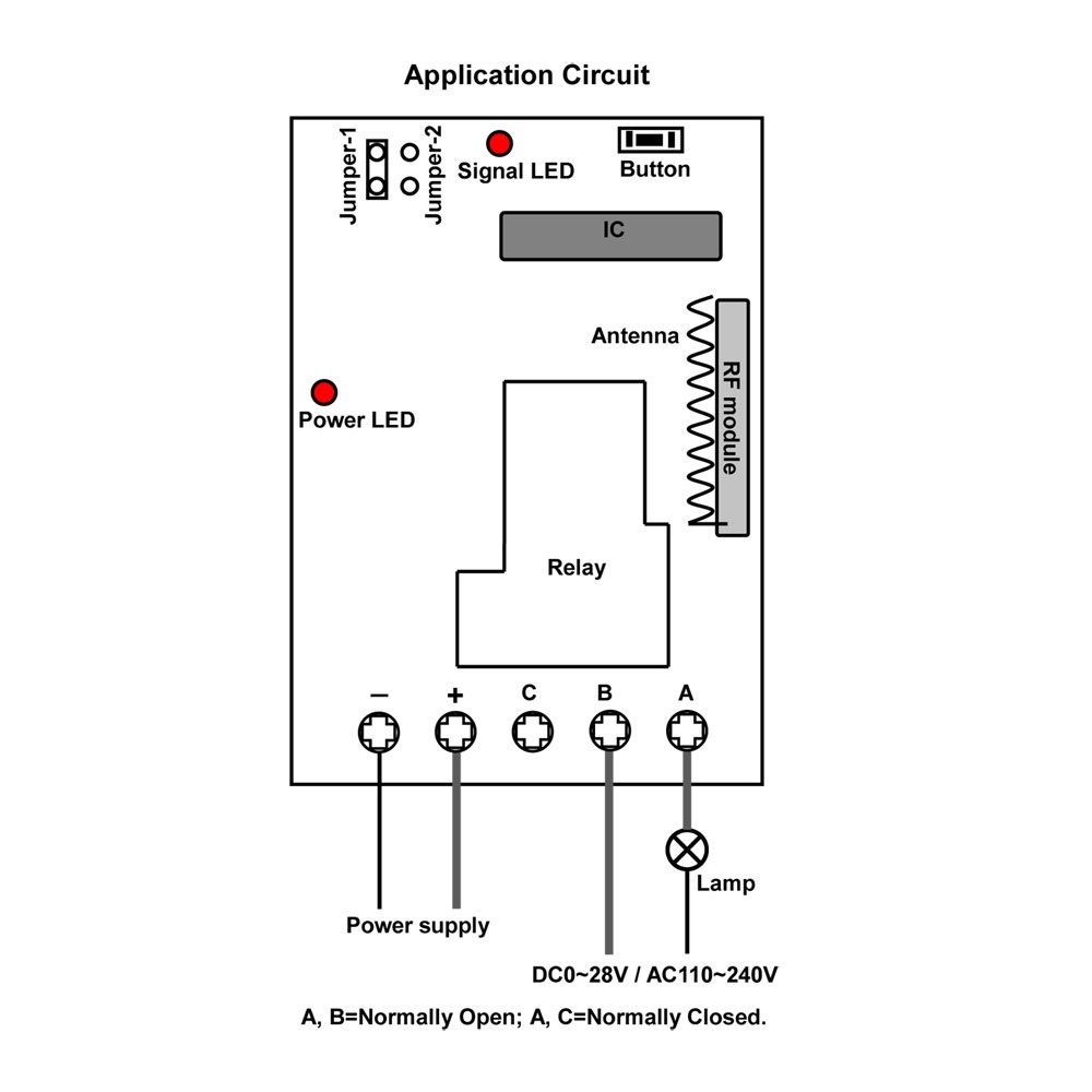
Please look at the circuit diagram below, you can learn how to wire your electric appliances to the receiver. The terminals A and B are normally closed, the terminals B and c are norminally open. That is the reason why it is called dry contacts. Output terminals L ans N should be wired to 220v AC power supply. The electric appliances should connect to the terminals B & C. At the same time we need supply additional power 220v AC to the electric appliances. There are four working modes of the remote control, the Momentary mode can meet the customer’s requirement. How is the Momentary mode set? The thing you only do is to connect Jumper-1 according to the following diagram.

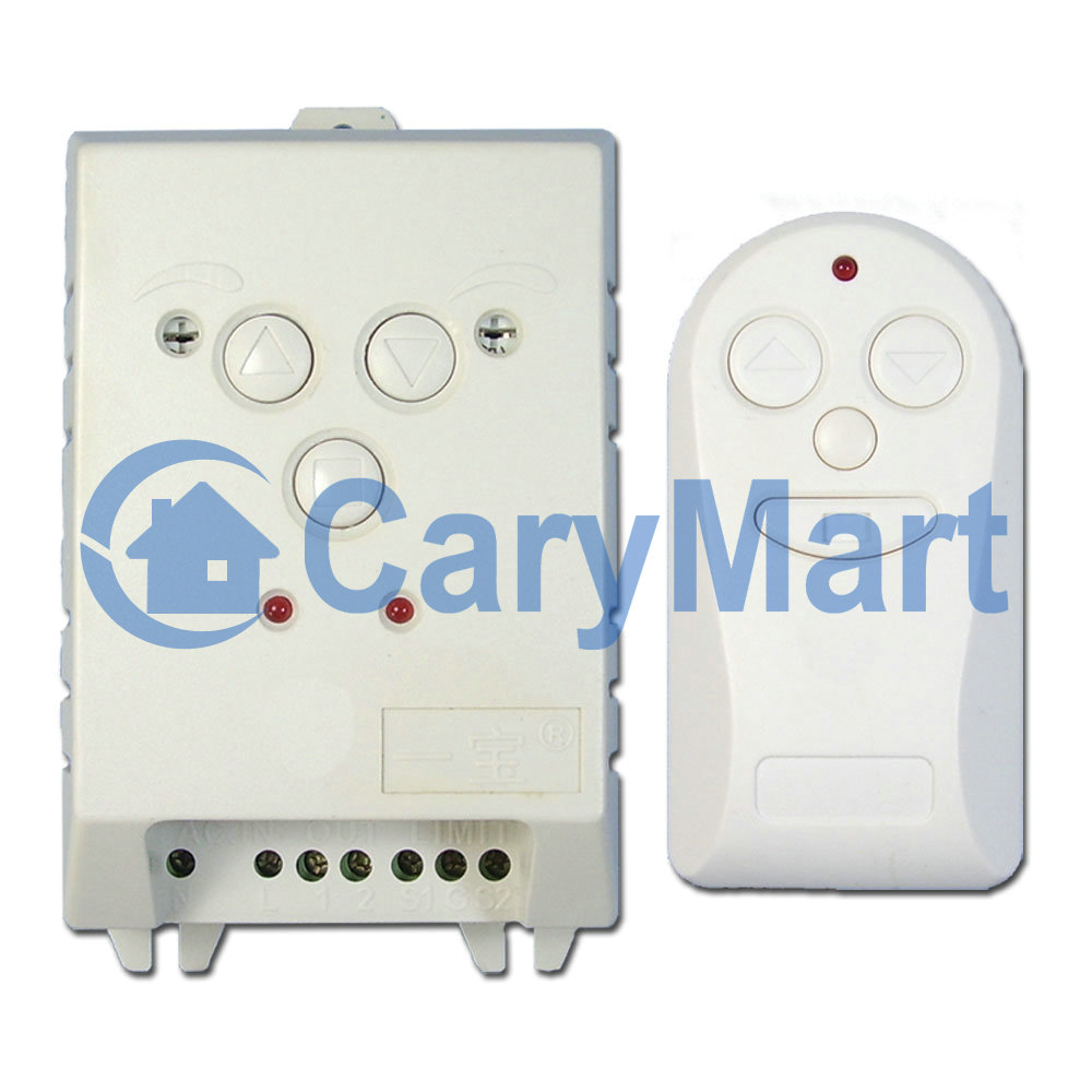
Model 0020333 (S2U-AC220 & C-2)
Website:
S2U-AC220
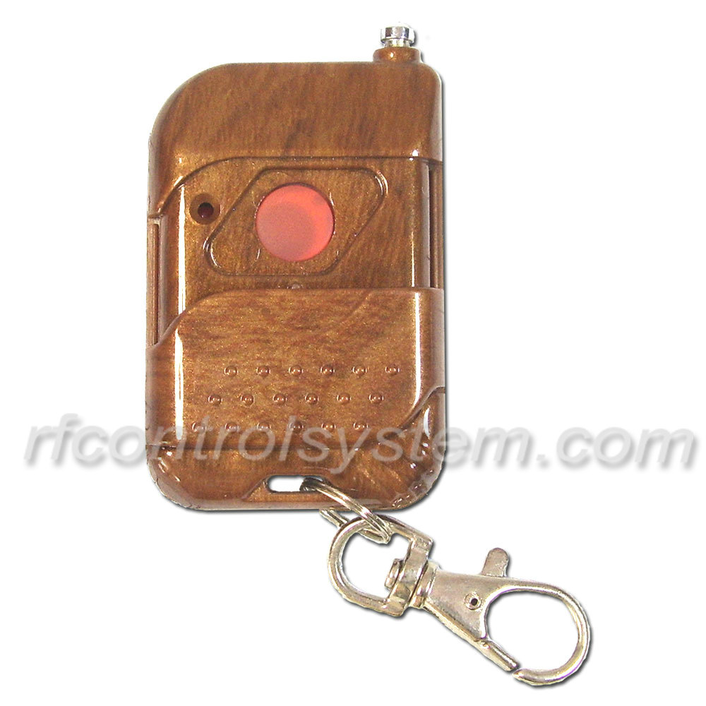
C-2
http://www.carymart.com/2-channel-learning-remote-control-range-100m-p-1508.html
 Follow