30amps 100M Remote Controller for Submersible Pump

Question from customer:

I am in Australia and here we have Live-Re and Neutral-Black and Earth-Green. I wish to wire a submersible pump to your radio controller then back to the consumer mains. Please advise if wiring would be.

Mains :

Live Red          to            Controller  Power Supply L

Neutral Black  to           Controller Power Supply N

Controller terminal A               to  Pump Live Red

Controller terminal B                    to Pump Neutral Black

What is the terminal C in the controller used for? How is the earth cable from the pump and the incoming power cable earth to be connected via the controller?

Answer:

We recommend you 1 channel 30amps remote controller kit (S1PU-AC220&C-2). This 1 channel 30A rf remote control kit operates in toggle, momentary and latched control mode (set the mode as you like freely). It is great for hard to reach electrical devices, remote distance is 100m. Control lights, motors, fans, electrically operated doors / locks / windows / blinds / cars or other appliances with voltage AC110~240V or DC0~28V.

1

The outputs of this receiver are relay outputs (the terminals are normally open and normally closed), they are not AC power outputs. It just amount to a switch to turn on or off device.

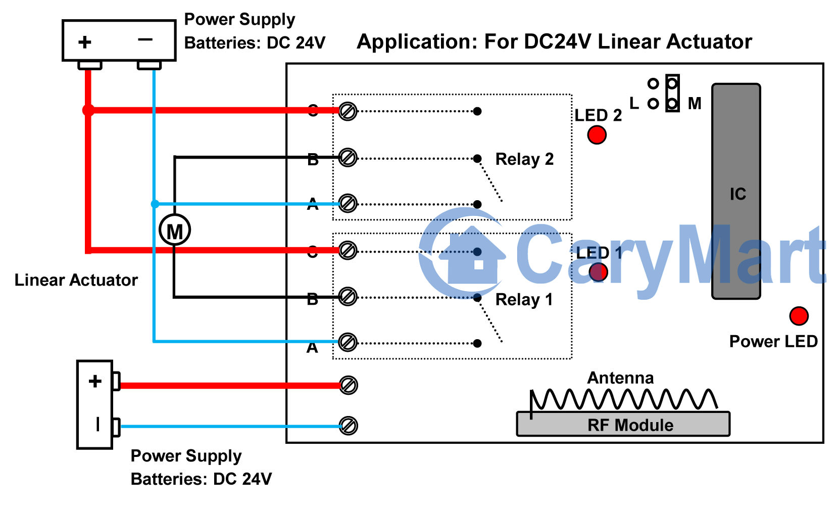
If you want to turn on / off the pump by this product, the connections are as following:

Live Red        to       Controller  Power Supply L

Neutral Black    to       Controller  Power Supply N

Live Red        to       Controller terminal B

Neutral Black    to       Pump Neutral Black

Controller terminal A   to           Pump Live Red

the earth cable from the pump  to     Earth – Green

circuit

Usage:

Setting control mode Toggle: Only connect Jumper-2. Control mode Toggle: Press -> On; Press again -> Off. Press button 1: Turn on the  submersible pump. Press button 1 again: Turn off the  submersible pump.

Setting control mode Momentary: Only connect Jumper-1. Control mode Momentary: Press and hold -> On; Release -> Off. Press and hold button 1: Turn on the  submersible pump. Release button 1: Turn off the  submersible pump.

Setting control mode Latched: Disconnect Jumper-1 and Jumper-2. Control mode Latched: Press -> On, other relays Off; Press another button -> Off. Press button 1: Turn on the submersible pump. Press button 2: Turn off the  submersible pump.

How to Remote Control Linear Motion Actuator Run Forward and Backward

Question from customer:

I have 24V Linear Motion Actuator which moves 2 ways (OUT and IN). Also I have 24V power Supply.

I would like to connect the remote control, and be able to open and close the actuator. Ideally, I want to press the button until actuator extends fully, and press another button to retract fully.

Linear Actuator

Answer:

We recommend this 2 channel wireless remote control momentary on off switch which is widely applied to lights, motors, fans, electrically operated doors / locks / windows / blinds, etc. One relay as an ON/OFF switch can turn on or off electric gadget. If you want to remote control  bidirectional motion, you may choose 2 channel remote (two relays). Your linear motion actuator can run forward and backward, so this remote is very available for you. It provides linear motion actuator with 10A. It is enough for linear motion actuator. With 2-button transmitter, its working distance reaches about 100m which can make your control range much wider, getting rid of narrow space constraint.

1

The wiring of linear motion actuator is a little sophisticated. See the following picture.

motor circuit

Initial state: A, B = Normally Closed; B, C = Normally Open.

So wire linear motion actuator to B terminals of two relays. Wire “C” terminals of two relays together to positive electrode of 24 batteries. Wire “A” terminals of two relays together to negative electrode of 24 batteries. And supply additional power to the receiver. It can avoid generating interfere between receiver and linear motion actuator.

Momentary mode is the only working mode in this remote. So press and hold button 1, linear motion actuator extends slowly, if you release button 1, it stops moving. Press and hold button 2, linear motion actuator retracts slowly, if you release button 2, it stops moving.

How to Remote Control 240V 25 amps Electric Equipment

Question from customer:

I am looking for an RF switch and transmitter where the switch has a coil voltage up to 12v and the switch terminal can handle 240v and 25 amps. Do you have anything like this?

Answer:

We recommend 1 channel high power remote controller (S1PU-DC12&C-2). The receiver is normally open and closed contact, so you can wire the gadget which is activated by AC 110~240V or DC0~28V.  The relay outputs 30amps current for gadget. It meets your needs. The receiver is run by 12VDC, but receiver and controller gadget will be supplied power separately so that they won’t interfere to each other. The transmitter is 2-button type remote. When it works with receiver together, their working distances reach 100m.

1_02

Here is the sample of wiring method.

Suppose that we remote control a lamp. The normally open terminals are A&B. The normally open terminals are A&C. Lamp should be connected to A&C terminals. Normally open and closed contact is similar with an ON/OFF switch. The being controlled gadget cannot get power from powered receiver. We should supply additional power to it. We can supply DC or AC power to controlled gadget according to its available power supply.

1_09

Toggle mode, momentary mode and latched mode are its working modes.

Setting control mode Toggle: Only connect Jumper-1.

Control mode Toggle: Press -> On; Press again -> Off.

Press button 1: Turn on the gadget

Press button 1 again: Turn off the gadget

Setting control mode Momentary: Only connect Jumper-2.

Control mode Momentary: Press and hold -> On; Release -> Off.

Press and hold button 1: Turn on the gadget

Release button 1: Turn off the gadget

Setting control mode Latched: Disconnect Jumper-1 and Jumper-2.

Control mode Latched: Press -> On, other relays Off; Press another button -> Off.

Press button 1: Turn on the gadget

Press button 2: Turn off the gadget

Temperature Controlling Digital Tube

This is the digital display tube circuit board. There are several buttons and terminals at circuit board. They are 12VDC power input and output terminals, 4 buttons S1 (SET), S2(+), S3(-), S4(LEARNING BUTTON), manual switch, temperature sensor and jumper from right to left.

IMG_2253-1

There are 3 controlling methods in it. They are manual switch control function, remote control function and temperature sensor control function. At first, we will introduce the code learning and manual switch control function.

Code Learning:

1) Press button S4; signal LED on the controller keeps shining. The controller enters into status of LEARNING.

2) Press any one button on remote control. If signal LED flashes quickly 5 times and turns off, it means learning is successful.

3) When controller is in the status of LEARNING, press again button S4, signal LED turns off, learning process will be discontinued.

4) The controller can learn several remote controls with different codes.

We have learned remote control to the controller. If you don’t want the controller to work with the remote control, you can delete all codes of remote controls, which are stored in the controller.

Operation: Press and hold S4 until signal LED flashes slowly; release the button, LED keeps slow flash. That means all stored codes have been deleted successfully.

Manual switch: to control positive, reverse rotation and stop of motor.

Working method: Move to “positive rotation” position, motor rotates in positive direction; move to “Stop” position, motor stops; move to “reverse rotation” position, motor rotates in reverse direction.

Here are two videos for your reference.

Code Learning Video:

Manual Switch Control Motor Video:

How to Remote Control Light with Sensor in a Long Distance

Question from customer:

Hello, I have a question about your products and a system I’m attempting to build. I have four sensors that give off about 5 volts when activated. When a sensor is activated I want to transmit a signal to a light and turn on a light.

The basic design is:

Sensor —> Transmitter  –>(Wireless)–> Receiver —> Light What I’m asking is what transmitter could I use with the 4 Channel Receiver? Would I need 4 separate transmitters for each of the sensors?

sensor 2

Answer:

We recommend the low current triggered transmitter (CB-2V) and the ac power direct output receiver (S1X-AC220).

remote controller

The transmitter is triggered by DC power 5~28V input. If low current input triggers transmitter, the transmitter will send RF signal to receiver to indicate it to work. The receiver has 1 Channel AC 110V/220V Power Output terminal contact. You don’t have to supply addition power to controlled device because the device will get power from powered receiver.

You can connect your sensor to the transmitter CB-2V, and connect your light to the receiver S1X-A220. Light is connected to L&N terminals of receiver and will get power when the receiver is connected to power supply.

tansmitter circuit


receiver circuit

When a sensor is activated, it can trigger a transmitter to transmit a signal to turn on a light. You need a separate transmitter for each of sensors.