Firework Ignition with Mobile Phone WIFI Controller

Mobile phone WiFi is so convenient to us nowadays. What’s more, we think mobile phone WiFi is not only used for internet surfing, but also can ignite firework when you use our mobile phone WiFi controller. It contains WiFi controller with 8 relays (WF-8-1R) and WiFi controller software which should be installed into your mobile phone. When your installed this software, your mobile phone will become the transmitter.

Let’s show you all how to use this mobile phone WiFi controller to ignite firework. Look at the following picture. Material includes WiFi controller, phone, firework, and line as well as 9V adaptor (power supply).

WF-8-R material

Here is the wiring.

WF-8-R wiring

Press WIFI controller software icon and press “Connect” icon. Set Momentary control mode: Press the ▼ icon of  channel 1. Choose M (Momentary) control mode.

WIFI-8-1R set M mode

Press the button to ignite firework.

WIFI-8-1R firework ignition


12-Channel Remote Control Pyrotechnics Ignition System Ignites Cascade Pyrotechnics

A new 12-channel remote control pyrotechnics ignition system has been added to our online store. It can ignite various kinds of electric fireworks directly, or cascade pyrotechnics which are used at stage. Remote control firework ignition reduces accidents like skin burn and accidental explosions.

12 channel firework ignition system

It contains 12-button remote transmitter and 12-channel ignitor. Each channel can ignite about 25 pyrotechnics simultaneously. It also has many features including test function, voltage indicator, waterproof case and manual operation mode. Wireless signal pass through walls, floors and doors. The remote control distance is 500m/1500ft (theoretically).

Let’s show you all how to use this remote control pyrotechnics ignition system.

First of all, we should prepare materials. We have firework ignitor and remote transmitter as well as cascade pyrotechnics.

S12PS1-ANT1&CB-12L material 2

Here comes to wiring. Wire cascade  pyrotechnics to the ignitor, the  pyrotechnics can be remotely controlled by remote transmitter from any place within a reliable distance.

S12PS1-ANT1&CB-12L wiring

Press button to ignite cascade pyrotechnics. The  pyrotechnics go off in a cascade of color.

S12PS1-ANT1&CB-12L firework ignition


4 Channel RF Remote Switch Controls Sliding Doors

One of our customers mounted an electric sliding door mechanism between his living room and outside swimming pool. It was started by dc electric motors and he would like to add a remote system to control it.

sliding_door 1

So we recommend him a remote control system. The 4CH RF remote switch operates in toggle, momentary, latched and toggle + momentary control mode (set the mode as you like freely). You can use it to complete four operations at the same time. For example, turn the light on, open the door or control other dc/ac electrical devices in the meantime. It is applied for light remote control, motor remote control, garage door remote control, gate remote control, etc.

4 channel remote control

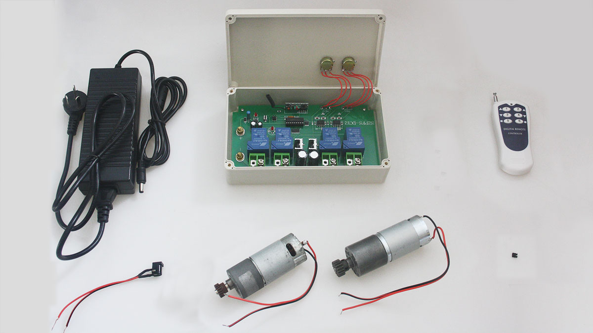
Here we’d like to show you how to control dc motor of sliding door rotate in positive and reverse direction. Firstly, we have the following material.

1×4-button dc rf remote receiver(S4C-DC12)

1×4-button transmitter (C-4)

2×dc motors

2×12V adaptors

Some lines

S4C-DC&C-4 preparation

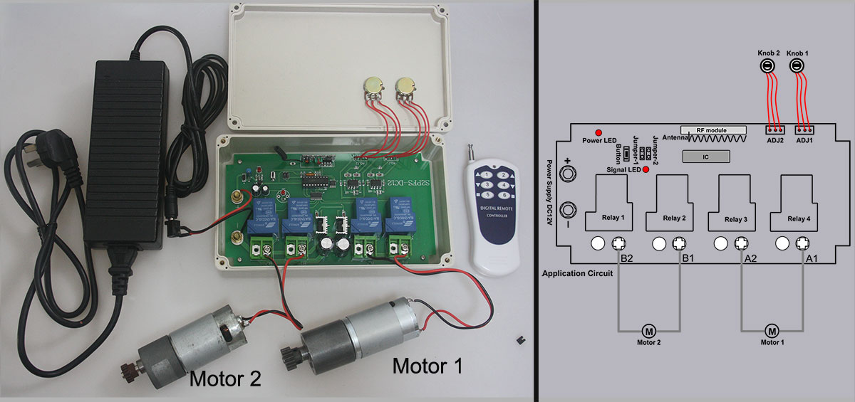
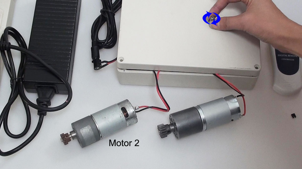
Secondly, it is the wiring. We will wire motors to receiver according to the wiring diagram. B is the common terminal. A is the closed terminal and C is the open terminal. Usually, one relay can only switch on and off one motor. Each two relays can control one motor rotate in positive and reverse direction. So we connect two motors to B terminals to every two relays respectively. Connect terminal C to the positive and connect terminal A to the negative.

application circuit


S4C-DC&C-4 wiring

Thirdly, it is operation. We choose momentary working mode: only connect Jumper-1.

Press and hold button 1, motor 1 rotates in positive direction. Release button 1, motor 1 stops.

S4C-DC&C-4 motor 1 button 1 positive rotation

Press and hold button 2, motor 1 rotates in reverse direction. Release button 2, motor 1 stops.

S4C-DC&C-4 motor 1 button 2 reverse rotation

Press and hold button 3, motor 2 rotates in positive direction. Release button 3, motor 2 stops.

S4C-DC&C-4 motor 2 button 3 positive rotation

Press and hold button 4, motor 2 rotates in reverse direction. Release button 4, motor 2 stops.

S4C-DC&C-4 motor 2 button 4 reverse rotation


How to Control Speed of Engine Rotation

Question from customer:

I need a control system for controlling a DC 12v engine, I seek to control the speed of rotation depending on the voltage applied.

Answer:

We recommend 2 channel motor speed remote controller—S2PFS-DC12 and CV-6-2.  By comparison with other motor remote controller, this controller S2PFS-DC can control speed of motor rotation. It won’t depend on the voltage applied because two speed control knobs on the receiver are to adjust the speed of two motors separately.  You can control two engines by one remote controller simultaneously. Maximum working current is 10A for each channel.

remote control model

You may be wondering how it works. Let’s show you how to control speed of two motor rotations.

1 x 2 channel dc remote control receiver (S2PFS-DC12)

1 x 6-button remote transmitter (CV-6-2)

1 x dc12v power adapters

2 x dc motors

S2PFS-material

Here comes the wiring.

Motor 1 is supposed to be connected to terminals A1&A2 at receiver. Motor 2 is supposed to be connected to terminals B1&B2 at receiver.

S2PFS-wiring-y 2

Speed Adjustable Operation

Besides ordinary starting and stopping operation, rotation for forward and reverse by transmitter, we mainly show that twist two knobs on the receiver to adjust the speed of rotation.

Knob 1 controls motor 1; Knob 2 controls motor 2.

For motor 2, twist the knob 2 anti-clockwise, the speed will be faster; twist the knob 2 clockwise, the speed will be slower.

S2PFS-DC+CV-6 motor2speed adjust COPY

For motor 1, twist the knob 1 clockwise, the speed will be slower; twist the knob 1 anti-clockwise, the speed will be faster.

S2PFS-DC+CV-6 motor1 speed adjust COPY


Wirelessly Romote Control Water Valve by Sprinkler Controller

Question from Customer:

I am trying to design and build a remote switch system for my sprinkler system. I need to use the sprinkler controller (12v output for on) to trigger a transmitter to switch a 12v operated valve on the other side of the yard (about 300m away.) I have mains power at both locations but the underground 12v wire from the controller has been damaged so I would like to build a remote system to save putting new conduit for around 300m across the yard.

Looking at your systems, the easy part would be the receiver end because I would only need a 12v power supply. The hard part will be getting the transmitter to switch on when the sprinkler controller switches on (12v).

sprinkler-controller

Answer:

We recommend direct power output high power long range remote control kit—S1PX-DC12-ANT2+CB-2V. The remarkable feature of this kit is that its transmitter is triggered DC power 5~28V input. That is to say, the transmitter will send out RF signal to receiver as long as it gets a 5~28V voltage from a device. Besides this advantage, its working distance is up to 2000m (6000ft). And the working current is 30amp. RF signal can pass through doors, walls and other obstacles.

remote control

Look at the following simulated diagram. The sprinkler control controls the valve box through the underground electrical wire initially. Unfortunately, the wire has been damaged. However, customer is unwilling to put new conduit for about 300m across the yard.

original wiring

So using our product to solve this problem is a wise choice. We connect the black wire of transmitter to the common wire of sprinkler controller; Connect the red wire of transmitter to wire from controller to valve. On the other hand, in the control valve box, valve common wire is supposed to be connected to the negative terminal of receiver; valve wire should be connected to the positive terminal of receiver. (As the following application circuit shown)

application circuit


Wiring modification

When you switch on sprinkler controller, the transmitter will be triggered by 12V voltage from sprinkler controller and sent out RF signal to indicate receiver to work. The valve is open and it starts the irrigation. Likewise, you switch off sprinkler controller, the triggered transmitter will indicate receiver to stop working. The valve is closed and it stops the irrigation.

There is no need to put new wire between sprinkler controller and valve control box. It is no longer the hardest part of getting transmitter to switch on when the sprinkler controller switches on.

irrigation 2