DC 12V Remote Control Switches AC 220V Triggered Modem

Question from customer:

I want to use your system to remote control turn on / off the power of the modem. I go from my office on the third floor of our home to the basement in order to turn off and disconnect the power to the modem. Then after a few minutes I reverse the process and reestablish the power to the modem and turn the modem on. The modem is power by an AC Adaptor (INPUT = 120-240V OUTPUT = 12V ).

modem

Answer:

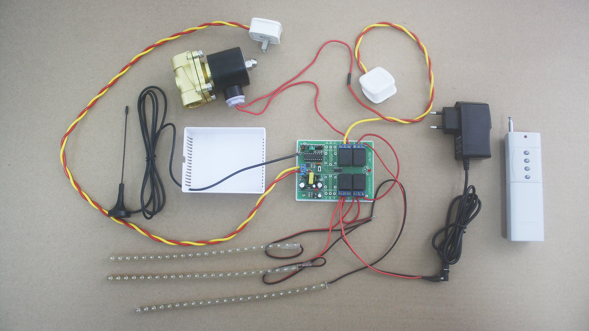
We recommend the model of 1 channel DC long range remote control kit (S1X-DC12-ANT2+1CB-2) to you. It can wireless control electric devices and  is easy to install. With direct power output, it means that you don’t need to supply power to the controlled device. It is capable of controlling lights, motors, fans, electrically operated doors/locks/windows/blinds/cars or other appliances.

You can turn on/off the receiver with transmitter (remote control) from any place within a reliable distance; the wireless RF signal can pass through walls, floors and doors. We add external extended antenna to it. The antenna can extend the controlling range to 2000M. So you can rest assured that signal can get through any obstacles to reach modem at your home.

1

As for your modem is powered by ac power, so you should connect the output of your AC Adaptor (12V) to two terminals + and – of this receiver, then connect two terminals A and B to your modem, then you can use our remote CB-2 to turn on / off the power of the modem.

You can set “Latched Mode”.

Press big button, turn on the modem.

Press small button, turn off the modem.

4 Channel RF Remote Switch Controls Sliding Doors

One of our customers mounted an electric sliding door mechanism between his living room and outside swimming pool. It was started by dc electric motors and he would like to add a remote system to control it.

sliding_door 1

So we recommend him a remote control system. The 4CH RF remote switch operates in toggle, momentary, latched and toggle + momentary control mode (set the mode as you like freely). You can use it to complete four operations at the same time. For example, turn the light on, open the door or control other dc/ac electrical devices in the meantime. It is applied for light remote control, motor remote control, garage door remote control, gate remote control, etc.

4 channel remote control

Here we’d like to show you how to control dc motor of sliding door rotate in positive and reverse direction. Firstly, we have the following material.

1×4-button dc rf remote receiver(S4C-DC12)

1×4-button transmitter (C-4)

2×dc motors

2×12V adaptors

Some lines

S4C-DC&C-4 preparation

Secondly, it is the wiring. We will wire motors to receiver according to the wiring diagram. B is the common terminal. A is the closed terminal and C is the open terminal. Usually, one relay can only switch on and off one motor. Each two relays can control one motor rotate in positive and reverse direction. So we connect two motors to B terminals to every two relays respectively. Connect terminal C to the positive and connect terminal A to the negative.

application circuit


S4C-DC&C-4 wiring

Thirdly, it is operation. We choose momentary working mode: only connect Jumper-1.

Press and hold button 1, motor 1 rotates in positive direction. Release button 1, motor 1 stops.

S4C-DC&C-4 motor 1 button 1 positive rotation

Press and hold button 2, motor 1 rotates in reverse direction. Release button 2, motor 1 stops.

S4C-DC&C-4 motor 1 button 2 reverse rotation

Press and hold button 3, motor 2 rotates in positive direction. Release button 3, motor 2 stops.

S4C-DC&C-4 motor 2 button 3 positive rotation

Press and hold button 4, motor 2 rotates in reverse direction. Release button 4, motor 2 stops.

S4C-DC&C-4 motor 2 button 4 reverse rotation


2-channel Wireless Remote Switch On and Off Light and Lock

One of our customers lives in large house in the countryside and enjoys a stretch of green field. Recently, he bought an adjustable time delay control kit from us because he wants to control his door lamp and lock beside the door. When he drives in and out, he can press button to open and close the door and even he can control lamp in the evening. (as the following picture shown)

This 2-channel wireless remote switch, which we provided, operates in time delay control mode. Adjustable delay time can be 0 second~99 hours. For its 2 channels, you can adjust delay time for two relays optionally according to your actual requirement. Our customer used it to turn on the lamp and open the door in the meantime.

We would like to show the simple procedure.

After preparing material, we do some wiring. Here is the wiring picture.

The remote control kit is installed on the wall. (The following is what customer did.)

The lamp and electric lock connect to normally open terminals B&C of relay 1 and relay 2 respectively. The customer adjusted delay time 1 minute for relay 1 and 30 seconds for relay 2. Button 1&3 controls relay 1; Button 2&4 controls relay 2. He drives in and out in the daytime, he can press button 1 to open the door. The door will close by itself after 30 seconds. Of course, he can press button 3 to close it immediately as soon as he goes out of the gate. In addition, lamp need to be turn on at night, he can press button 2 to turn on the lamp. And he can press button 4 to switch off the lamp at once or let it go out by itself.

How to Remote Control Electromagnetic Lock

Electromagnetic lock is a locking device that consists of an electromagnet and an armature plate. The principle behind an electromagnetic lock is the use of electromagnetism to lock a door when energized. Essentially it consists of an electromagnet attracting a conductor with a force large enough to prevent the door from being opened.

electromagnetic lock copy

That is to say, if only we could cut off power supply and make electromagnet force between electromagnet and armature plate to disappear, the door would be opened. Furthermore, we just try to use a direct dc output momentary remote and one button transmitter to cut off electric power to open the door. The following demonstration will show.

At first, we prepare material.

material preparation copy

The wiring

wiring

When we supply power to electromagnetic lock, electromagnet will attract armature plate through magnetic force. The door is locked. When we press button, the power supply will be cut off. The door is open as soon as electromagnetic lock unlock instantly.

operation

What’s more, this rf remote control sends out rf signal which can pass through walls, doors as well as other barriers. You can remote control the electromagnetic lock to open the door as long as you stay within a reliable distance.


Wireless Automatic Garden Watering System and Remote Control Lamps

Question from customer:

Can you help me select the correct product? The distance is 600 feet through house with walls and some trees. I need to turn on a 220 volt garden watering system for my plant. There is a solenoid valve connecting to the spray head of the system. I also want to turn on at least three other dc 12 volt circuits separately for lights.The control panel has a switch on it right now that I would like to be able to still use if necessary.

garden-irrigation-system

Answer to this question:

We recommend this four function distant-range rf remote .  The working voltage range of relay is AC 110—240V or DC0~28V. The highlight of this product is that it can activate different electrical devices with different working voltage simultaneously.There are totally four channels. It is 10amp current for each channel. The working distance is up to 2000m (6000FT) in open air with external mount antenna. It is very appropriate for garden watering system.

remote control kit

We make a demonstration of this remote controlling.

Let’s look at the following material.

S4U-AC-ANT2&CB-4 remote control led material

As seen in the picture, three spotlights should be connected three relays’ normally open terminal individually and be supplied DC 12 V power supply. The pond fountain will be connected to last one relay’s normally terminal and be supplied AC220V power supply.

S4U-AC220-ANT2+ CB-4电路图及视频拍摄说明

S4U-AC-ANT2&CB-4 wiring

There are 4 buttons on the transmitter. One button controls one relay. Usually, we set “Toggle Mode”.

So press button “A”, turn on the led light strip 1.

S4U-AC-ANT2&CB-4-operation1-A on


Press button “B”, turn on the led light strip 2.

S4U-AC-ANT2&CB-4-operatio1-B on


Press button ‘C”, turn on the led light strip 3.

S4U-AC-ANT2&CB-4-operation1-C on


Press button “D”, turn on the solenoid valve.

S4U-AC-ANT2&CB-4-operation1-D on


Press buttons one by one again to switch off all of them.

S4U-AC-ANT2&CB-4-operation D off