Question from customer:
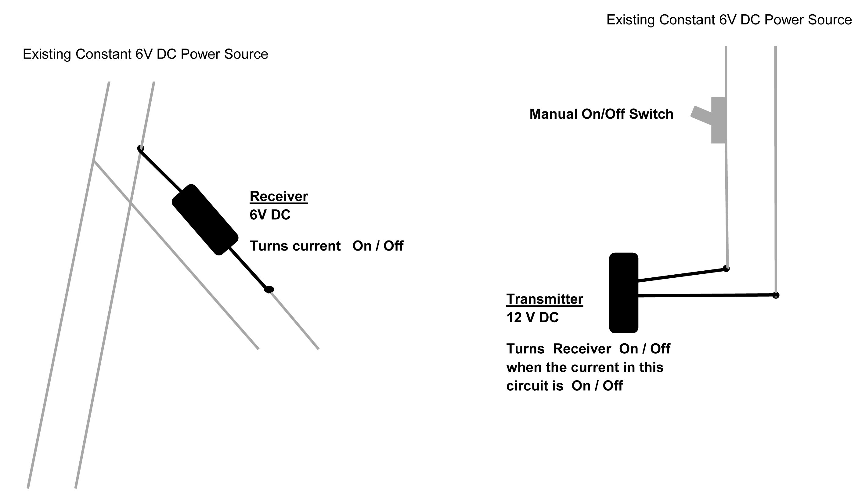
I want a remote controlling unit that the transmitter is to function as a switch to the receiver activated by supplying a 12V DC current to the transmitter (switch it on). The receiver then allows a 6V DC current to be supplied to a designated appliance. When the transmitter is shut off the receiver will shut down.
Answer:
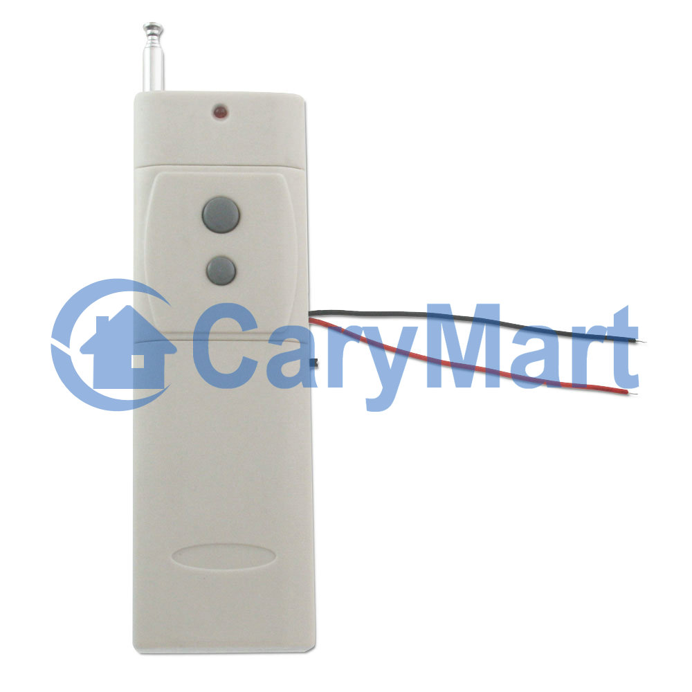
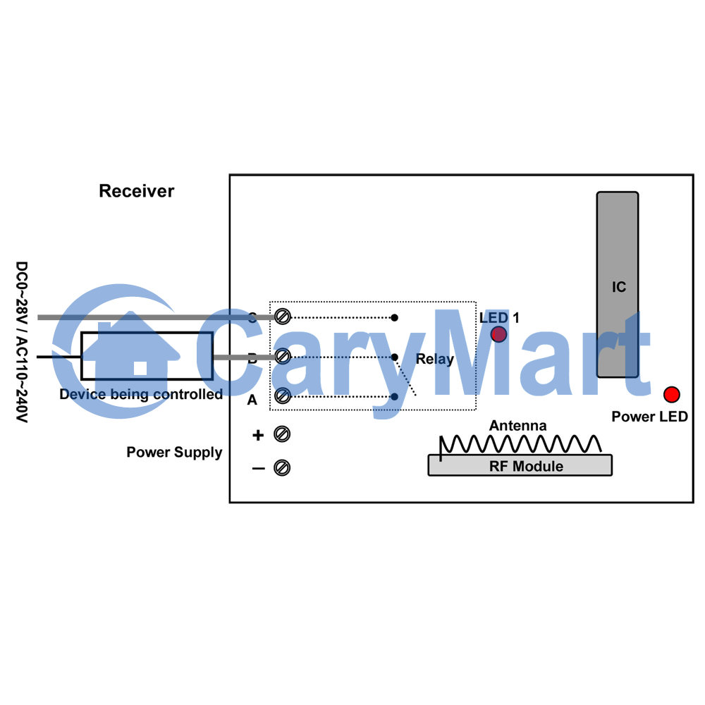
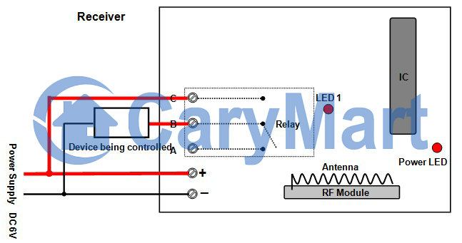
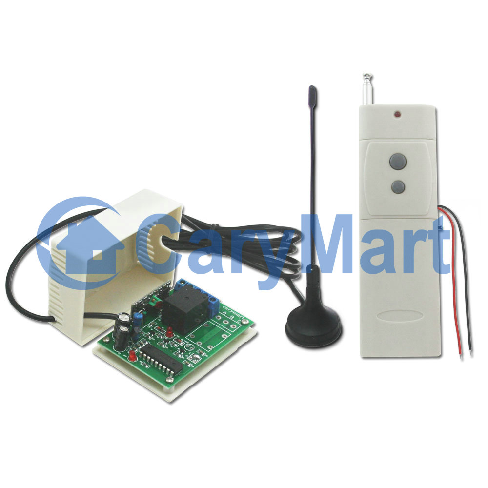
Maybe this kind of controlling unit —6V power direct output RF remote control system (S1XL-DC06-ANT2+CB-2V) is suitable for you. It is activated directly by 6V power supply. You don’t have to supply additional power to the device being controlled because the controlled device will get power from powered receiver. It is specially designed for device controlling another device. The remarkable characteristic of the transmitter CB-2V will be triggered by DC power 5~28V input. We add external extended antenna which makes transmitting distance up to 2000m.
According to the picture above, he wants the transmitter can be activated by manual switch and turn receiver on/off when the current in that circuit is on/off. First, the transmitter is supposed to be connected to power supply and that manual switch. Second, designated appliance should be connected to receiver.

We prepare a demonstration for this practical use.
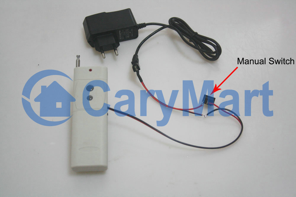

We switch on the manual switch and the transmitter will send an “ON” signal to the receiver. The receiver receives the signal to instruct the light to turn on. We switch off the manual switch and the transmitter will send an “OFF” signal to the receiver. The receiver receives the signal to instruct the light to turn off.
 Follow