RF Remote Control System is Applied at Private Airport

Overview:

“I am looking for a remote and multiple receivers for a small private airport. We have a controller box switch that activates when you key the microphone 7 times on a specific frequency. I would like to plug a dc power adapter into this unit and wire into one of your remotes. The runway lights are all solar dc leds. I will need 12 receivers total to start out. My question is: Can one remote, controlled by external wires, send a signal out to multiple receivers at the same time?  In other words, if the remote detects dc input and sends out an ON signal, can several receivers receive the ON signal at the same time?”

airport runway lightsairport runway light 2

Solution:

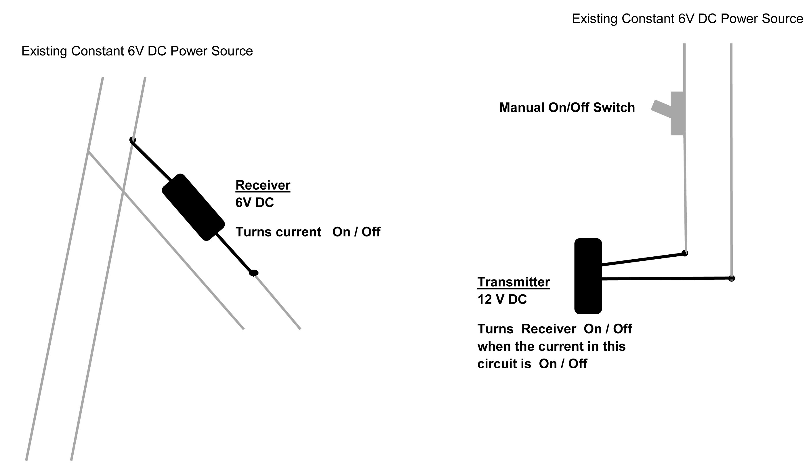
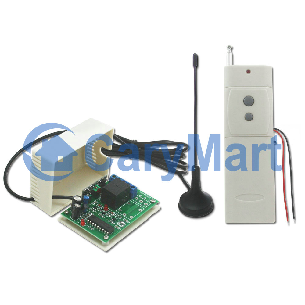
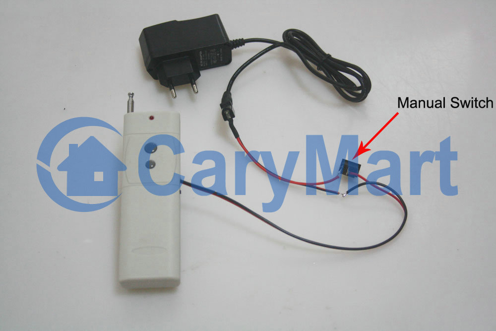
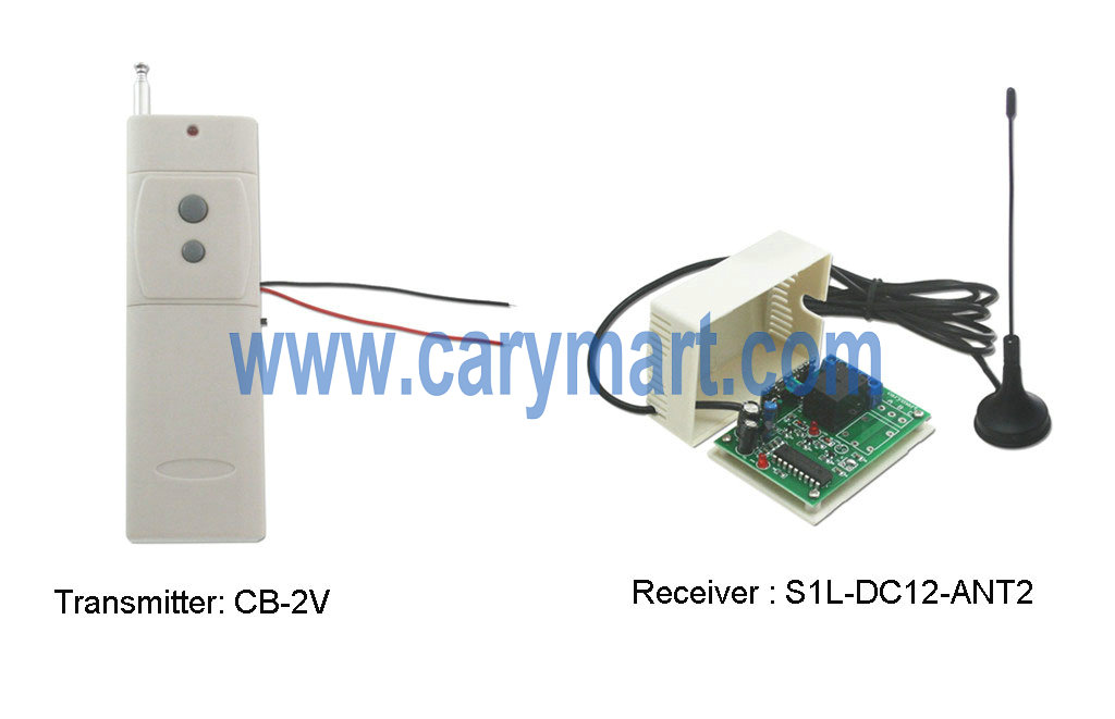
We recommend the low voltage triggered transmitter (CB-2V) and 1 channel 2000m receivers (S1L-DC12-ANT2). The most remarkable feature of this transmitter is low current triggered. That is to say, when you offer dc power 5~28V to this transmitter, it will send signal out to the receiver. The receiver is long range with external extended antenna. When it works in pairs with transmitter, their transmitting distance can reach 2000m (6000ft) in the open field. One transmitter can send out ON signal to make several receivers ON at the same time if you use the same code of those transmitter and receivers.

remote-control-kit

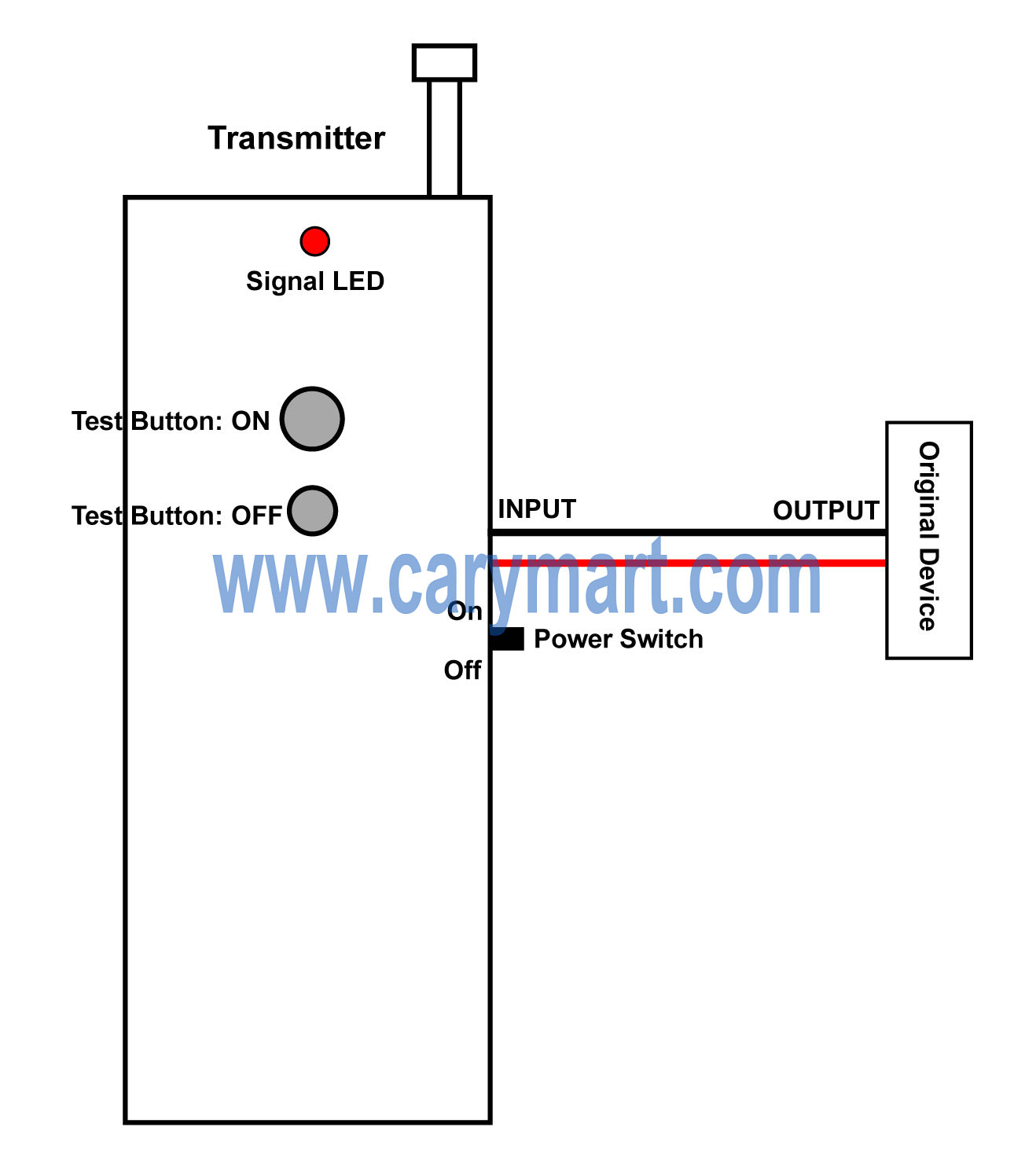
Wires on the transmitter should be connected to the contacts of original device which can generate dc 5~28V output power.

circuit-of-transmitter

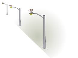
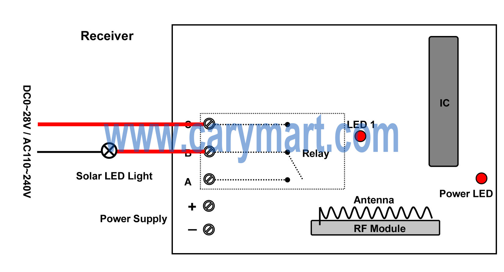
The normally open contacts B&C of receivers should be connected to solar led light being controlled. Wire each solar led light to each receiver.

circuit-of-receiver

When the contacts of two wires of transmitter input 5~28V voltage, the transmitter is triggered and then transmits an rf signal “ON” to the receiver. After the receiver receives the signal, contacts B&C are closed; the solar led lights being controlled are on.

When the contacts of two wires of transmitter’s power is cut, the transmitter is triggered and then transmits an rf signal “OFF” to the receiver. After the receiver receives the signal, contacts B&C are cut; the solar led lights being controlled are off.

6V Output RF Remote Control System Apply for Device Control Another Device

Question from customer:

I want a remote controlling unit that the transmitter is to function as a switch to the receiver activated by supplying a 12V DC current to the transmitter (switch it on). The receiver then allows a 6V DC current to be supplied to a designated appliance. When the transmitter is shut off the receiver will shut down.

RF 6V DC

Answer:

Maybe this kind of controlling unit —6V power direct output RF remote control system (S1XL-DC06-ANT2+CB-2V) is suitable for you. It is activated directly by 6V power supply. You don’t have to supply additional power to the device being controlled because the controlled device will get power from powered receiver. It is specially designed for device controlling another device. The remarkable characteristic of the transmitter CB-2V will be triggered by DC power 5~28V input. We add external extended antenna which makes transmitting distance up to 2000m.

1_01

According to the picture above, he wants the transmitter can be activated by manual switch and turn receiver on/off when the current in that circuit is on/off. First, the transmitter is supposed to be connected to power supply and that manual switch. Second, designated appliance should be connected to receiver.

S1XL-DC12circuit

We prepare a demonstration for this practical use.

CB-2V-and manual switch

S1X-DC+CB-2V-lamp on

We switch on the manual switch and the transmitter will send an “ON” signal to the receiver. The receiver receives the signal to instruct the light to turn on. We switch off the manual switch and the transmitter will send an “OFF” signal to the receiver. The receiver receives the signal to instruct the light to turn off.

Manual Switch on/off to Remote Control LED On the Receiver

Question from customer:

I want a remote controlling unit that the transmitter is to function as a switch to the receiver activated by supplying a 12V DC current to the transmitter (switch it on). The receiver then permits a 12V DC current to be supplied to a designated appliance. When the transmitter is shut off the receiver will shut down.

T R 12V DC #3

Answer:

Maybe this kind of controlling unit —12V power Input RF remote control system (S1XL-DC12-ANT2+CB-2V) is suitable for you. It is applied for device controlling another device. The characteristic of the transmitter CB-2V will be triggered by DC power 5~28V input. We add external extended antenna which makes transmitting distance up to 2000m.

1_01

According to the picture above, he wants the transmitter can be activated by manual switch and turn receiver on/off when the current in that circuit is on/off. First, the transmitter is supposed to be connected to power supply and that manual switch. Second, designated appliance should be connected to receiver.

S1XL-DC12circuit

We prepare a demonstration for this practical use.

CB-2V-and manual switch

We switch on the manual switch and the transmitter will send an “ON” signal to the receiver. The receiver receives the signal to instruct the light to turn on. We switch off the manual switch and the transmitter will send an “OFF” signal to the receiver. The receiver receives the signal to instruct the light to turn off.

S1X-DC+CB-2V-lamp on

Long Range Communication System (Remote Control Application)

Question from customer:

I need a remote valve setup for a nitrogen purging system.The valve is 100volt 10amp that needs to be controlled by latching switch setup. I’ve seen many setups everywhere that will work but my problem is that I need some sort of indications, such as a led lamp or something at the remote to verify whether the valve is open or not. Do you have something like this available?

Feasible solution:

We found a solution to solve your problem. We also made a simulation test.

You need feedback to the remote or another receiver with a signal light to verify remotely that the valve is open. We’d like to prepare two sets of remote control and make them a remote control group. The main system is 1 channel 12VDC output receiver (S1XL-DC12)+ long range transmitter (CB-2). The secondary system is still 1 channel 12VDC output receiver (S1XL-DC12) , but we use dc triggered transmitter (CB-2V, triggered method DC power 5~28V input), which is applied for one device controlling another device. That is to say, the transmitter will send out RF signal to receiver as long as it gets a 5~28V voltage from a device.

The following picture is the material preparation.

S1XL-DC&CB-2&CB-2V material COPY

When you add the external extended antenna, you will make the remote controller working distance to 2000M in the open air.

0020276 S1PUA-AC110Antenna wire

Here is the wiring diagram.

2S1XL-DC12-ANT2+CB-2V+CB-2 circuit

The wired transmitter (CB-2) will work with Receiver 1 as one group. The wireless transmitter (CB-2V) will work with Receiver 2 as another group. We have a wired remote transmitter at the first receiver that it will remotely turn on a lamp at the second receiver near the wireless transmitter.

S1XL-DC&CB-2&CB-2V wiring COPY

Operation:

Press big button of wireless transmitter (CB-2), send “ON” RF signal to the first receiver, turn on lamp 1(blue lamp) and trigger wired transmitter (CB-2V), wired transmitter switch on lamp (red lamp) on the second receiver.

S1XL-DC&CB-2&CB-2V big button lamp ① on

S1XL-DC&CB-2&CB-2V- big lamp② on later

Press small button of wireless transmitter (CB-2), send “OFF” RF signal to the first receiver, turn on lamp 1 (blue lamp) and trigger wired transmitter (CB-2V), wired transmitter switch off lamp 2 (red lamp) on the second receiver.

S1XL-DC&CB-2&CB-2V -small button lamp① off

S1XL-DC&CB-2&CB-2V -small button lamp② off later

We can get feedback through red lamp to verify whether the controlled device (Blue lamp) is working or not.

Video: