Wireless Switch and Adjustable Time Delay Receiver for DC Light

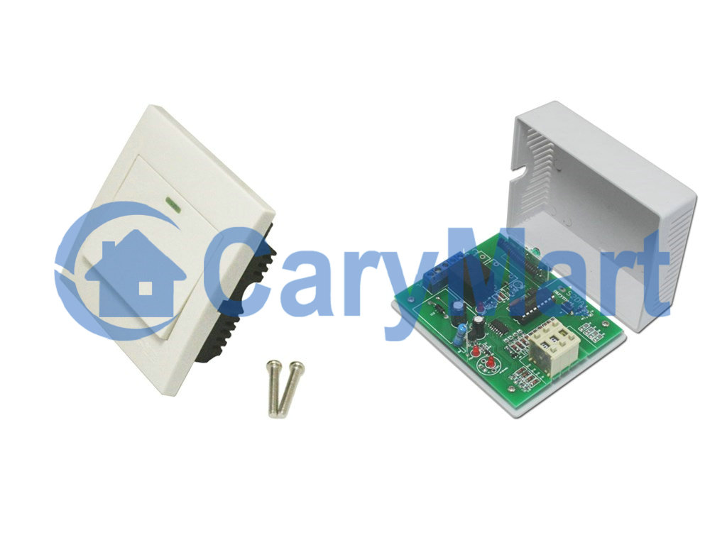
We can use wall mounted wireless rocker switch and time delay adjustable receiver to control DC lamp.

The wireless rocker switch belongs to remote control calling system, which is the hi-tech electronic product which is integrated wireless communication and computer technology. It is widely applied to restaurants, coffee shops, karaoke rooms, discos, sauna rooms, beer houses, pubs, night clubs, bowling alleys, golf courses, video halls, hotels, hospitals, schools, chain stores ,shops… Time delay adjustable receiver has the range of time adjusting 0 second~99 hours. With normally open& closed terminal contact, we can wire DC or AC device to it. We are going to let them work together to build a new remote control system.

rocker switch& receiver

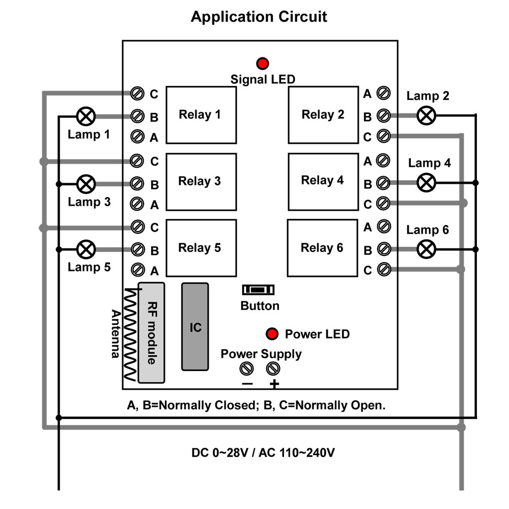
At first, we should pair up wireless rocker switch and adjustable time delay receiver. Then, we install the rocker switch to wall with screw. Next, we wire DC lamp to receiver. Initial state: A, B= Normally Closed; B, C =Normally open. So DC lamp should be wired to B, C terminals. Supply power to DC lamp and receiver respectively.

1_09

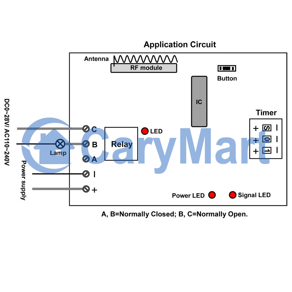
Press buttons of “+” and “-” on the timer, adjust delay time from 0 second to 99 hours. “H” is Hour, “M” is Minute, and “S” is Second.

For example, supposed we set “M 0 1”, it means the delay time is 1 minute.

Press button on the rocker switch, turn on the lamp. After delay time, lamp will turn off by itself. If we want to turn off lamp immediately, press button on the rocker switch again, lamp turns off, no need to wait for delay time.

Wireless Remote Control Transmitter by Connecting Wires to the equipment with 6 relays

Question from customer:

   I can use 4 each of the 6 relay/channel receivers. I cannot use a handheld remote with buttons. I need 4 transmitters that I can control each transmitter with 6 switch / contact     closures. There will be no one there to push a button. Basically there will be 6 relays external to the transmitter that will serve as the input to the transmitter. When any one of the relays operate the transmitter will cause the corresponding relay to close in the receiver. I have  to be able to match each transmitter with one of the receivers so there will be no interference between them.

 Answer:

   According to your requirement, we advise you to use the facility: it is model S6C-DC12-ANT2 & CB-6. The receiver has 6 relays (S6-DC12-ANT2) and the transmitter has 6 switches (CB-6). You can connect 12 wires of transmitter to the 6 relays in your equipment. That means the relay can control the transmitter. When one of the relays in the equipment operates and the relay to close, the transmitter will launch RF wireless signal with remote control. The RF wireless signal can pass through walls, floors and doors, then can be received by the receiver.

   It can control lights, motors, fans, electrically operated doors/locks/windows/blinds/cars or other appliances with AC110~240V or DC0~28V. You can turn on/off the appliances with transmitter (remote control). And the working distance of remote control is 2000m/6000ft theoretically because of the receiver with external extend antenna (ANT2).

        Receiver                                                                                                                                       

1_02


  Transmitter

1_10


  Here is the circuit diagram. You can connect the transmitter to the 6 relays in your equipment. Then supply power to the receiver. The transmitter can be activated by the relay normally closed and launch RF wireless signal with remote control.

1_07


If you would like to know more something about wireless remote control transmitter by relays in the equipment, please you enter into our website and search the product as following:

Model: 0020456 (S6C-DC12-ANT2 & CB-6)

Website:

http://www.carymart.com/


http://www.carymart.com/index.php?main_page=advanced_search_result&search_in_description=1&categories_id=&keyword=S6C-DC12-ANT2