Temperature Controlling Digital Tube

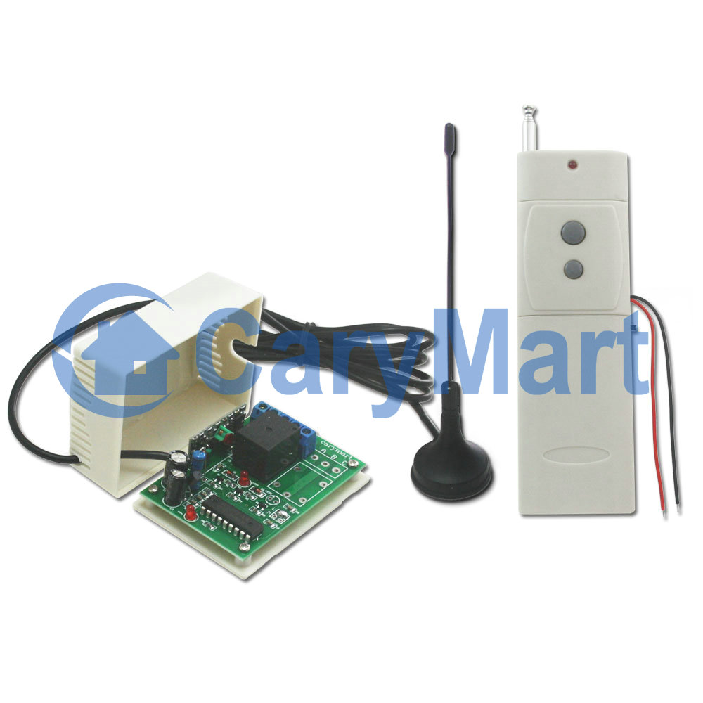
This is the digital display tube circuit board. There are several buttons and terminals at circuit board. They are 12VDC power input and output terminals, 4 buttons S1 (SET), S2(+), S3(-), S4(LEARNING BUTTON), manual switch, temperature sensor and jumper from right to left.

IMG_2253-1

There are 3 controlling methods in it. They are manual switch control function, remote control function and temperature sensor control function. At first, we will introduce the code learning and manual switch control function.

Code Learning:

1) Press button S4; signal LED on the controller keeps shining. The controller enters into status of LEARNING.

2) Press any one button on remote control. If signal LED flashes quickly 5 times and turns off, it means learning is successful.

3) When controller is in the status of LEARNING, press again button S4, signal LED turns off, learning process will be discontinued.

4) The controller can learn several remote controls with different codes.

We have learned remote control to the controller. If you don’t want the controller to work with the remote control, you can delete all codes of remote controls, which are stored in the controller.

Operation: Press and hold S4 until signal LED flashes slowly; release the button, LED keeps slow flash. That means all stored codes have been deleted successfully.

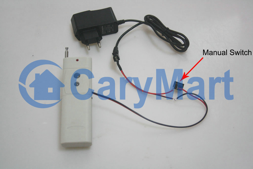
Manual switch: to control positive, reverse rotation and stop of motor.

Working method: Move to “positive rotation” position, motor rotates in positive direction; move to “Stop” position, motor stops; move to “reverse rotation” position, motor rotates in reverse direction.

Here are two videos for your reference.

Code Learning Video:

Manual Switch Control Motor Video:

6V Output RF Remote Control System Apply for Device Control Another Device

Question from customer:

I want a remote controlling unit that the transmitter is to function as a switch to the receiver activated by supplying a 12V DC current to the transmitter (switch it on). The receiver then allows a 6V DC current to be supplied to a designated appliance. When the transmitter is shut off the receiver will shut down.

RF 6V DC

Answer:

Maybe this kind of controlling unit —6V power direct output RF remote control system (S1XL-DC06-ANT2+CB-2V) is suitable for you. It is activated directly by 6V power supply. You don’t have to supply additional power to the device being controlled because the controlled device will get power from powered receiver. It is specially designed for device controlling another device. The remarkable characteristic of the transmitter CB-2V will be triggered by DC power 5~28V input. We add external extended antenna which makes transmitting distance up to 2000m.

1_01

According to the picture above, he wants the transmitter can be activated by manual switch and turn receiver on/off when the current in that circuit is on/off. First, the transmitter is supposed to be connected to power supply and that manual switch. Second, designated appliance should be connected to receiver.

S1XL-DC12circuit

We prepare a demonstration for this practical use.

CB-2V-and manual switch

S1X-DC+CB-2V-lamp on

We switch on the manual switch and the transmitter will send an “ON” signal to the receiver. The receiver receives the signal to instruct the light to turn on. We switch off the manual switch and the transmitter will send an “OFF” signal to the receiver. The receiver receives the signal to instruct the light to turn off.