Reversible motor is a motor in which the direction of rotation can be reversed by means of a switch that changes motor connections when the motor is stopped. If you want to control a DC reversible motor, you may choose a wireless remote control kit.
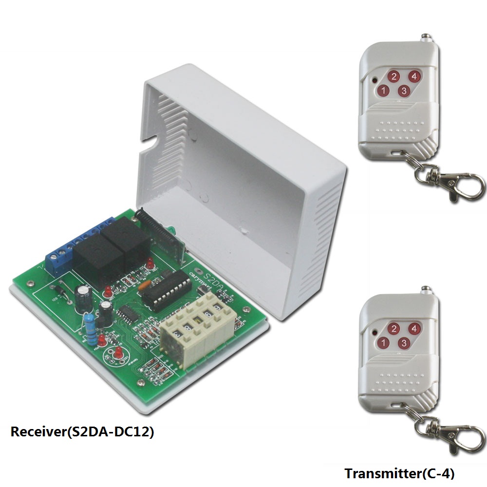
Model 0020320 (S2DA-DC12 & C-4) is a wireless remote control kit with adjustable time delay function which is work for DC Equipments. The receiver model 0020319 (S2DA-DC12) is 2 channels and input voltage is DC 12V. It is an adjustable time delay control mode. Adjustable delay time can be 0 second – 99 hours. The transmitter model 0021003 (C-4) has 4 buttons and has a sliding cover which can protect the button when you slide the cover up.
With such combination, you can easily complete two operations at the same time. For example, turn the light on and open the door in the meantime. Applications include gate remote control, motor remote control, garage door remote control, light remote control, etc.
Here is an application that you can use this kind of kit to control a DC reversible motor:
One of our customers wants to use a wireless remote control kit to control a DC12V motor. The kit should have the following function: When press the button 1 of the transmitter, the motor is in forward direction, then it will stop automatically after delay 12 seconds. When press the button 2 of the transmitter, the motor is in reverse direction, after 12 seconds delayed time it will turn back to the starting point and stop automatically. Then we recommended him Model 0020320 (S2DA-DC12 & C-4).
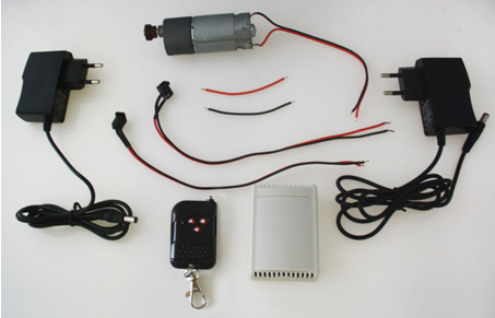
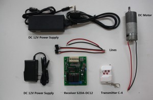
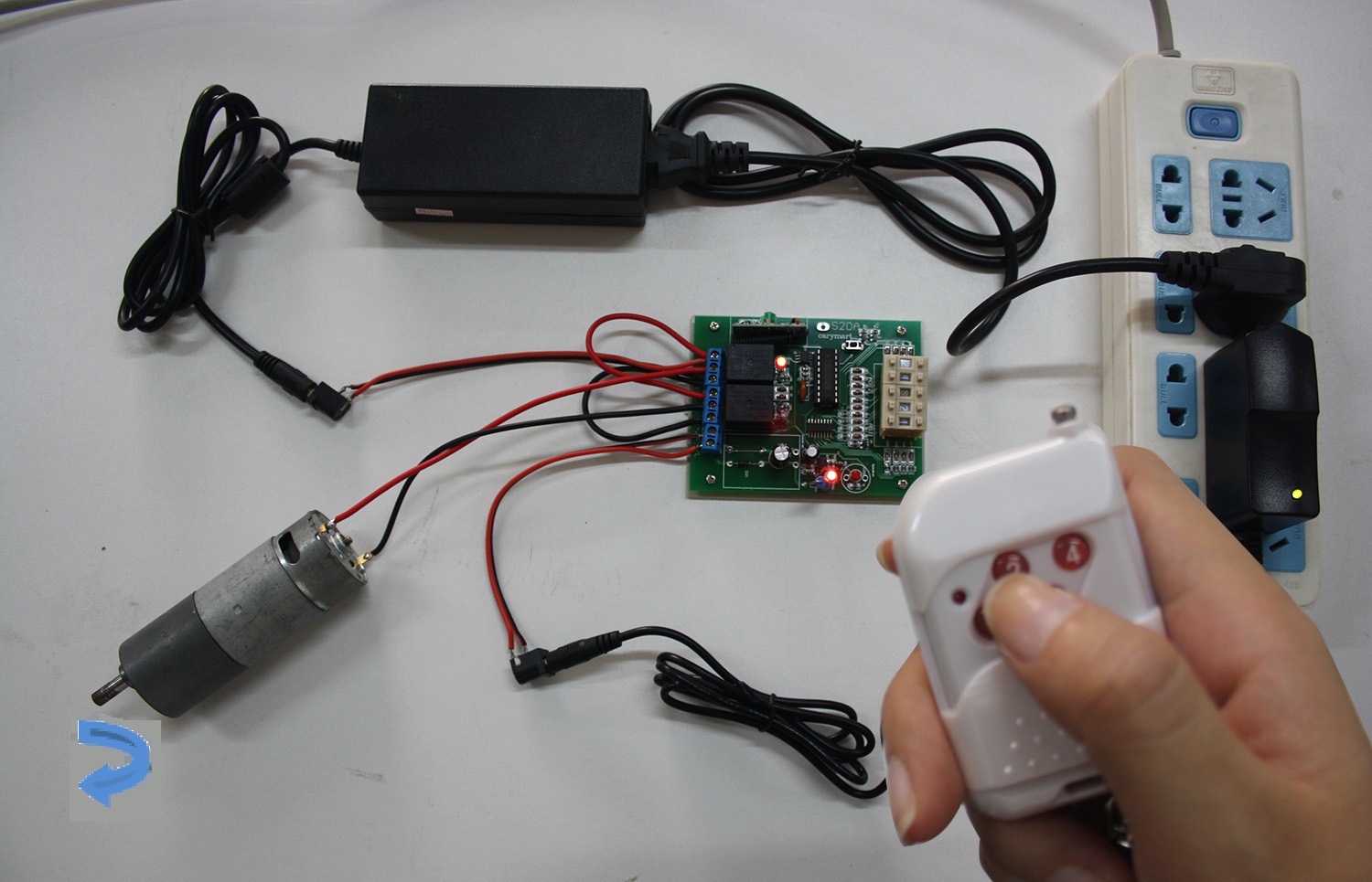
First of all, let’s see material preparation.
1 x 2 channel adjustable time delay remote control receiver (S2DA-DC12)
2 x 4-button remote transmitter(C-4)
2 x DC12v power adapters
1 x DC12V motor
Some lines
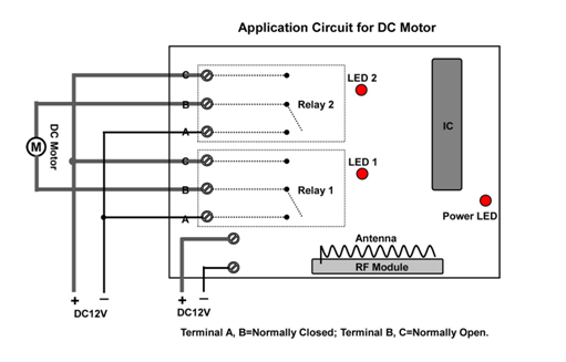
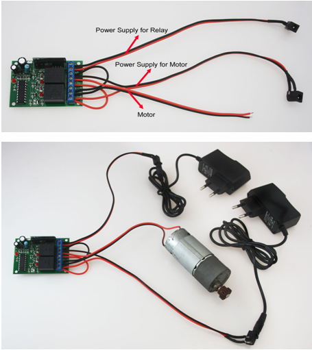
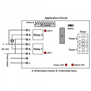
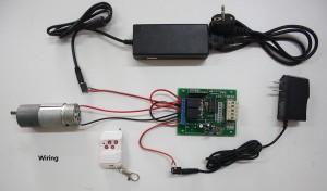
Secondly, see the wiring circuit diagram below. According to the circuit diagram, C is normally open terminal; A is normally closed terminal and B is common terminal. Connect terminal A to the negative pole and connect terminal C to the positive pole. Terminal B is supposed to be connected to the motor.
Note: The Power supply of receiver and motor must be provided individually in order to avoid interference between them.
Operation:
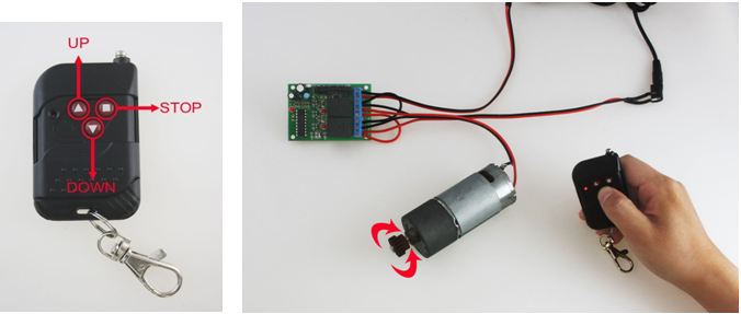
Press button 1, relay 1 turns on, the motor rotates in forward direction;
After delay time: The relay 1 will turn off by itself.
Press button 3, motor stops rotating (No need to wait for delay time).
Press button 2, relay 2 turns on, the motor rotates in reverse direction;
After delay time: The relay 2 will turn off by itself.
Press button 4, motor stops rotating (No need to wait for delay time).
You may ask how to set the delay time, do as followings:
Press buttons of “+” and “-” on the timer, adjust delay time from 0 second to 99 hours. Two buttons of Timer 1 adjust delay time of relay 1; two buttons of Timer 2 adjust delay time of relay 2. “H” is Hour, “M” is Minute, and “S” is Second.
In the above case, the customer may set “1 2 S 1 2” on Timer, it means the delay time on Timer 1 is 12 seconds, the delay time on Timer 2 is 12 seconds. Then he can achieve the whole operation.
 Follow