There are two types of wireless remote transmitters: electromagnetic waves and infrared. The working distance of the infrared remote transmitter is short, and the infrared ray can only be transmitted through the straight line, and can’t bypass the barrier. RF remote transmitter uses the RF signal, it is transmitted in all directions, and the signal can cross a certain barrier. The electromagnetic wave wireless remote control system uses the transmitter to transmit the electromagnetic wave, and the receiver extracts the electromagnetic wave and triggers various devices. The electromagnetic wave wireless remote control system commonly used in burglar alarm equipment, industrial equipment, doors and windows remote control, car remote control.
The following describes a commonly used four-button wireless remote control transmitter, the parameters are as follows:
Working voltage: DC12V (23A / 12V battery)
Working current: 10mA / 12V
Modulation method: ASK
Frequency: 315MHz / 433MHz
Coding type: fixed code
Working distance: 100 meters
Remote control/transmitter consist of buttons, coding circuit, a modulation circuit, signal amplifier and antenna. The principle of working transmitter: It first generates a specific wireless signal by the key, then the signal pass through the coding circuit, modulation circuit, signal amplifier circuit. Finally, radio waves are emitted through the antenna.


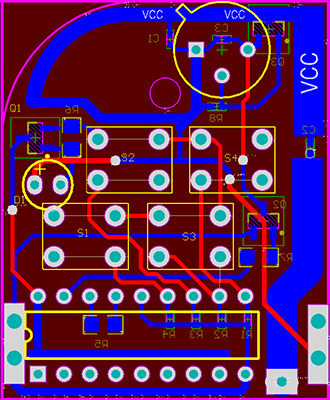
Four-button wireless remote control transmitter circuit PCB diagram
Four-button wireless remote control transmitter usually uses PT2262 or SC2262 encoding chip.The PT2262 or SC2262 is a low-power encoding chip fabricated in CMOS technology. The PT2262 or SC2262 has up to 12-bit (A0- A11) address-side pins. These pins can be left floating, connect the high level or connect the low level.They can combine up to 531441 sets of codes. The PT2262 or SC2262 has up to six (D0-D5) data-side pins that allow them to combine different data.A complete code consists of address code, data code and synchronization code,this code from pin 17 of PT2262 or SC2262 chip to the data input of the remote control terminal.After the receiving module receives the wireless signal, the decoder chip will compare and verify the signal, and the corresponding data pin of the decoder chip outputs the high-level signal to the amplifying circuit.
The pin diagram of PT2262 or SC2262 is as follows: 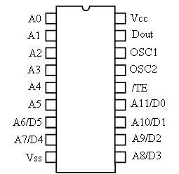
Pin Description:
| Name | Pin | Description |
| A0~A11 | 1~8、10~13 | Address pin, for address coding, can be set to “0”, “1”, “f (dangling)” |
| D0~D5 | 7~8、10~13 | Data input |
| Vcc | 18 | Positive power supply |
| Vss | 9 | Negative power supply |
| TE | 14 | Coding start-end |
| OSC1 | 16 | Oscillation resistance input |
| OSC2 | 15 | Oscillation resistance output |
| Dout | 17 | Coded output |
 Follow