The coding mode of radio remote control: fixed code and learning code

The wireless remote control system is a device used to control the machine remotely, it was first developed by Nicola Tesla in the United States in 1898. There are two common remote control systems on the market, one is IR Remote Control, which is commonly used in various household appliances, such as TV and air conditioning; the other is the RF Remote Control, which is commonly used in anti-theft alarm equipment, door and window remote control, car remote control and so on.

The radio remote control system (RF Remote Control) is a remote control device that uses radio signals to control a variety of equipment in the far distance. These radio signals can be received by remote receiving devices, which can drive all kinds of other mechanical or electronic devices to complete various operations, such as a closed circuit, mobile device and actuate motor. Radio remote control has been widely applied in the garage door, electric door, road gate remote control, burglar alarm, industrial control and wireless intelligent home.

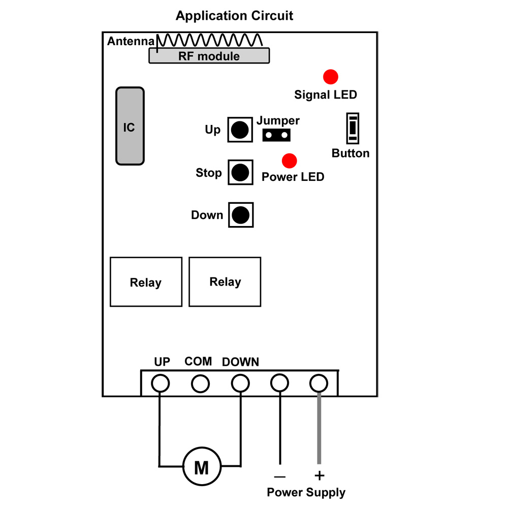
Radio remote controls system including a radio transmitter and a radio receiver. The transmitter mainly contains the coding circuit and the transmitting circuit. The coding circuit first generates the control instruction and then transmits the instruction signal to the transmitting circuit. The transmitting circuit loads the instruction signal on the high-frequency signal and then is sent to the wireless signal by the transmitting antenna. The receiver consists of a receiving circuit and a decoding circuit. Receiving circuit first amplifies the weak signal received, and then forwarded to the demodulator, the demodulators identify the signal, and then the amplifier circuit drives various devices.

There are two types of coding commonly used for radio remote control: fixed code and learning code.

Fixed code:

  1. The fixed wireless remote control code using 2260/2262/2264 encoding chip, Its code is set by a soldering iron
  2. The coding capacity of the fixed code is 6561, so the amount of the code is limited, the probability of the code repetition is high.
  3. Mainly used for relatively low-security requirements of the occasion.
  4. If the user wants to increase the number of remote controllers, the new remote controller will be set to the same code as the old remote controller. The new remote controller and the old remote controller can work at the receiver at the same time.
  5. If the remote control is lost, the user can set the receiver together with the new remote control to a separate code so that the remote control can no longer be controlled and the receiver can no longer be controlled.

learning code

  1. The learning code wireless remote control uses 1527/2240/101 and other coding chips, and the remote control does not need to be coded again when it is used.
  2. The encoding capacity of the learning code is 1 million, and the code repetition rate is low.
  3. It is mainly applied to occasions with higher safety requirements.
  4. If users want to increase the remote control, they only need to use the receiver to learn and store the code of the new remote controller, so the new remote controller and the old remote controller can work at the receiver at the same time. Usually, the receiver can store more than a dozen different codes.
  5. If the remote controller is lost, the user can use the receiver to delete the code of the old remote controller, then learn and store the code of the new remote controller, so that the lost remote controller can no longer control the receiver.

Remote Control Motor

Question from customer:

I’m looking for a wireless remote control kit to remote control motor of lawnmower in 800ft. Any suggestions?

700-590742

Answer:

We recommend the model of 500m/1500ft RF motor controller (S1FC-DC09/12/24 & CV-4-2) to help you remote control motor of lawnmower. The controller is activated by DC 9V, 12V and 24V. It is usually for motors of rolling blinds, doors, projection screens, awnings, pumps, winches, conveyor or other appliances and machines. It features in forward-reverse-stop capability which can make motor rotate in positive or reversal direction. With maximum transmission distance of 500m/1500ft, it can satisfy your requirement. Inner circuit of this kit uses the RF technology for making a wireless remote, which can make motor controlled by transmitter from any places with in reliable distance, this configured wireless signal can pass through walls, doors or floors or other solid obstacles.

1_13_1

Here is the wiring.

At first, we connect power line to terminals “+” and “-”. Secondly, we connect the receiver to the lawnmower actuator motor. Lawnmower motor is wired to UP and DOWN terminals of receiver. At last, we add power supply to receiver. You can exchange “UP” and “DOWN” lines of the motor to change rotating direction of the motor.

1_06

There two working modes in it.

Set Momentary control mode: Do not connect Jumper.

Press and hold button ▲ on remote or receiver: Terminals UP and DOWN output + DC9V / DC12V / 24V (UP: +, DOWN: -), lawnmower actuator motor rotates continuously in positive direction.

Release button ▲ on remote or receiver: Stop the motor.

Press and hold button ▼ on remote or receiver: Terminals UP and DOWN output - DC9V / DC12V / 24V (UP: -, DOWN: +), lawnmower actuator motor rotates continuously in reversal direction.

Release button ▼ on remote or receiver: Stop the motor.


Set Latching control mode: connect the Jumper.

Press button ▲ on remote or receiver: Terminals UP and DOWN output + DC9V / DC12V / 24V (1: +, 2: -), lawnmower actuator motor rotates continuously in positive direction.

Press ■ on remote or receiver: Stop the motor.

Press button ▼ on remote or receiver: Terminals UP and DOWN output - DC9V / DC12V / 24V (1: -, 2: +), lawnmower actuator motor rotates continuously in reversal direction.

Press button ■ on remote or receiver: Stop the motor.


By using this kind of wireless remote control kit, you can easily remote control motor.

Online shop: www.carymart.com

The differnece between relay output and DC/AC power output

What is the differences between relay output and DC/AC power output? Carymart will tell you.

Relay output: In a switch where the contacts remain in one state unless actuated, the contacts can either be normally open (abbreviated “n.o.” or “no”) until closed by operation of the switch, or normally closed (“n.c.” or “nc”) and opened by the switch action. Our remote receiver can be grouped into two types according to its current output modes. They are normally open/closed switch connection or current direct output connection (Controlled device can get power from powered receiver directly).

One customer sent a picture of “Normally Open/Closed Receiver Connecting to an AC Lamp” to us to ask whether it is correct or not.

100

Unfortunately, it is a wrong wiring. Please see a red cross to the lamp wiring from the following picture. This red cross points out the wrong wiring. AC lamp should not wire to the normally open terminals of receiver because there is no current through them which are only equivalent to a switch.

}]4G[2]JK)3D~`C]DFFG9O4

The correct wiring is as follow. This is the 1 channel normally open/ closed ac receiver (S1U-AC220) wiring. AC lamp is connected to normally open terminals B&C. And add a wire between terminals B&N and another wire to terminals C&L. At last, wire a plug to terminals L&N. Then, we finish the wiring.

300

400

Another customer attempted to install the unit model: 0020483 (S1DA-AC220-ANT2 & CB-2) to time his water heater pump. Everything on the remote unit seems to work OK except that he cannot get voltage from the unit to the pump to make it run.

He installed the wires as follows:

From house/wall AC 120v power black (line) on L, white (neutral) on N.

TO the pump, Black (line) on B, and white (neutral) on C. Timer works fine, however with timer LED light on he get no voltage from A, B, or C. He has checked the terminals with a multi meter and there is no voltage out to the pump. Also he checked the continuity of the cord to the pump–it is OK.

Then why did water heater pump don’t work?

The answer is he didn’t wire the water heat pump correctly.

The receiver he bought is relay output, not AC power output. So the wiring is incorrect. He should also connect black (line) of AC 120v power to terminal C, connect terminal B to Black (line) of the pump, and connect white (neutral) of AC 120v power to white (neutral) of the pump.

Look at this picture, Model: 0020504 (S1U-DC12-ANT2 & CB-2L) , the receiver is relay output, not DC/AC power output, the connection is definitely wrong; the lamps didn’t connect any power supply, so it can’t work.

1

Here is the circuit diagram.

Usually, when the receiver is relay output, the wiring operation should be as follow:

Connect DC power to terminal “+” and “-“.

Initial state of relay output terminals: Terminals B and C are Normally Open; Terminals A and B are Normally Closed.

Terminal B and C should also connect a DC/AC power supply to make the lamp work.

23

This is the correct connection.

4

Model: 0020424 (S1X-DC06/09/12/24 & C-2) is DC power output, the wiring is easier compare to model:0020504 (S1U-DC12-ANT2 & CB-2L) , which is relay output

When choosing the DC power output unit, you just need to connect DC power to terminals “+” and “-”, and connect lamp to terminals “A” and “B”.

Here is the circuit diagram:

5

Generally speaking, the wiring differences between relay output and DC/AC power output is that you should also connect a power supply to Normally Open terminal when your receiver is relay output model.

Online shop: www.carymart.com

How to wire water heater pump correctly?


A customer attempted to install the unit model: 0020483 (S1DA-AC220-ANT2 & CB-2) to time his water heater pump. Everything on the remote unit seems to work OK except that he cannot get voltage from the unit to the pump to make it run.

He installed the wires as follows:

From house/wall AC 120v power black (line) on L, white (neutral) on N.

TO the pump, Black (line) on B, and white (neutral) on C. Timer works fine, however with timer LED light on he get no voltage from A, B, or C. He has checked the terminals with a multi meter and there is no voltage out to the pump. Also he checked the continuity of the cord to the pump–it is OK.

Then why did water heater pump don’t work?

The answer is he didn’t wire the water heat pump correctly.

The receiver he bought is relay output, not AC power output. So the wiring is incorrect. He should also connect black (line) of AC 120v power to terminal C, connect terminal B to Black (line) of the pump, and connect white (neutral) of AC 120v power to white (neutral) of the pump.

Usually, when the receiver is relay output, the wiring operation should be as follow:

Take  model:0020504 (S1U-DC12-ANT2 & CB-2L) as an example:

Connect DC power to terminal “+” and “-“.

Initial state of relay output terminals: Terminals B and C are Normally Open; Terminals A and B are Normally Closed.

Terminal B and C should also connect a DC/AC power supply to make the lamp work.

Here is the circuit diagram.

2 3

This is the correct connection.

4


Model: 0020424 (S1X-DC06/09/12/24 & C-2) is DC power output, the wiring is easier compare to model:0020504 (S1U-DC12-ANT2 & CB-2L) , which is relay output

When choosing the DC power output unit, you just need to connect DC power to terminals “+” and “-”, and connect lamp to terminals “A” and “B”.

Here is the circuit diagram:


5


Generally speaking, the wiring differences between relay output and DC/AC power output is that you should also connect a power supply to Normally Open terminal when your receiver is relay output model.

Long Range Remote Control lights

If you want to long range remote control lights for the track, we can recommend you a series of long range remote control kits.

Here is the detail information:

One of our customer need to set up “warning” lights for the track and he ideally this would be done with wireless switching. Then he found us and said that our RF DC transmitters and receivers of the long distance type are what he is looking for to long range remote control lights. He then sent us a diagram to explain what he needed.

filename-1

The signal needs to travel at least 500 meters so the 2000m setup would be best. The receivers will trigger emergency flashing beacons.
The layout is for motorcycle oval track competition and the transmitters and receivers need to be operated by officials to ensure the safety of all competitors. This is done by operating warning revolving beacons. For this reason the customer need our best operating combinations over a distance of probably 800 to 1000 meters with direct line of sight available to remote control lights….so he gather the 2000m Long Distance combination (with separate antenna) would be the best option.
12 volt equipment is being used for all emergency lighting via a 12 Volt DC power source.
MP1,MP2,MP3 and MP4 are corner marshalling points and the transmitters only need the ability to switch the corresponding relay for that corner (MP1 to L1, MP2 to L2, MP3 to L3 and MP4 to L4 yellow on diagram).There needs to be no interference between each of these MP points so they can be operated independently of each other. Therefore each MP transmitter only needs to be one (1) channel.
CC1-Is the main central control for the marshalling and is operated by the steward of the event. The Steward will be mobile so this transmitter will not be at any fixed point. To enable the Steward to have total control and over-ride the operations of officials at all MP points this transmitter will need to be of 6 Channel operation, one channel for each MP (yellow) point (channels 1 to 4) and one channel (number 5) to operate simultaneously all RED receivers on points L1, L2, L3 and L4. This is to enable the stoppage of a race at any time by switching to a “STOP” light at all these points. Button number 6 can be spare.
SG1 – Is for the operation of the starting mechanism for each race (which could be up to 100) during the event.
This transmitter needs to be 2 Channel to enable the switching of 2 GREEN (GL1 and GL2)lights at the starting area from Channel 1 and Channel 2 will activate 2 solenoids (SR1 and SR2). Therefore transmitter needs to be 2 channel and SR1, SR2, GL1 and GL2 receivers all each need to be 1 channel. GL1 and GL2 have to operate simultaneously from Channel 1 and SR1 and SR2 have to work simultaneously from Channel 2.

According to all the information he has mentioned above, we recommend him a series of long range remote control kits to remote control lights. The theoretical working distance of the wireless remote control kits can reach about 5000m.

1


These remote control kits have feedback function and two ways working mode.

With the feedback function, they can let the user know whether he/she had already connected the transmitter and receiver successfully in such a long distance.

Here is the principle of the feedback function.


[Transmitter]   <———

|                         \

[Encode]                       \

|                            |

[Channel]                [Feedback]

|                            |

[Decode]                       /

|                          /

[Receiver]     ———->


Two ways working mode: When the receiver gets the signal of transmitter, it will immediately send a return signal to the transmitter. When the transmitter receive the feedback signal of the receiver, the transmitter will exude a buzzing sound like “D~” which means it receive the feedback signal successfully.

The receiver is waterproof case with waterproof connectors. The receiver can be installed outdoors. They are also high power remote control kits, each relay output can work at maximum current 30A.

External magnetic sucker antenna with 5meters cable, the antenna can be installed outside the building to get better working distance

The remote control kits can be used to remote control lights, agriculture automation, industry automation, and home automation. It can control products on land, water and air, especially in a long distance, such as business signs, motorboat, farm, pasture, offshore unmanned operation, field call, remote security alarm, unmanned aerial vehicle, etc.