Heavy Duty DC Motor Remote Switch with Manual Switch and Limit Switch Function

Heavy duty dc motor controller features remote control, manual switch and limit switch function. It is capable of controlling DC motors of rolling blinds / doors, projection screens, awnings, pumps, winches, conveyors or other appliances and mechanicals with voltage DC12V / 24V. Motor can be rotated in positive or reversal direction with the transmitter (remote control) or manual switch on the receiver or limit switch from any place within a reliable distance; the wireless signal can pass through walls, floors and doors.

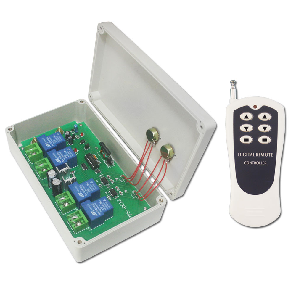
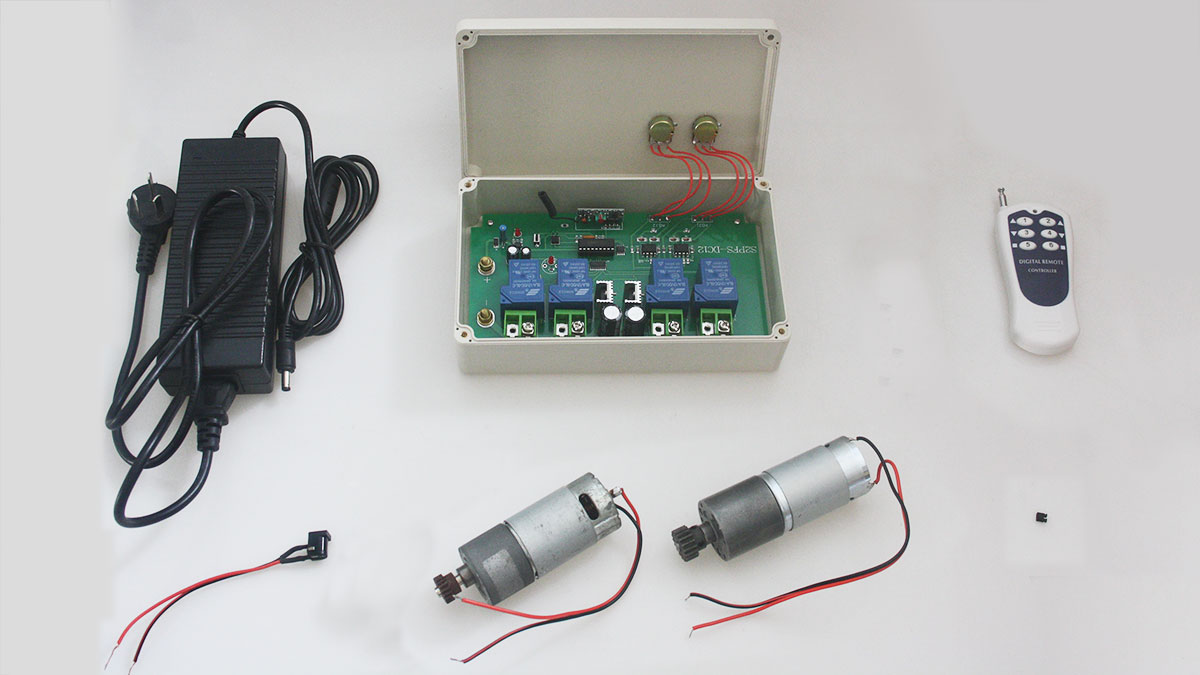
We will try to show you the demonstration of this motor controller. First of all we prepare RF receiver, transmitter, dc motor, 12V adaptor, and jumper.

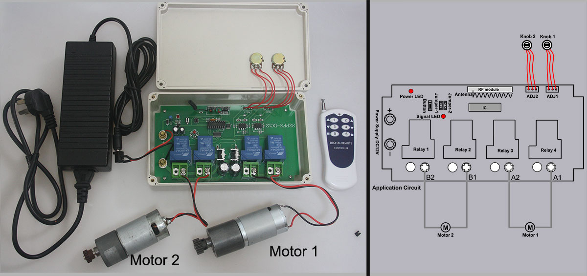
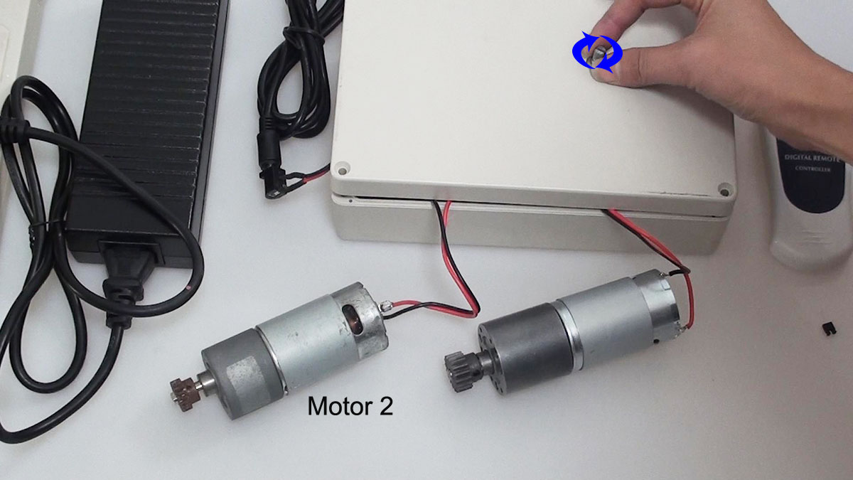
According to the wiring diagram, we connect the motor to the “OUTPUT” terminal on the receiver and connect 12V adaptor to “INPUT” terminal.

At first, we try to control motor with manual switch. Setting control mode Momentary: Do not connect Jumper.

Press and hold button S3 on receiver: motor rotates in positive direction. Release button: motor stops.

Press and hold button S1 on receiver: motor rotates in reversal direction. Release button: motor stops.

Second, we try to use transmitter to control motor. We use another working mode “Latched’ Mode. Setting control mode Latched: Connect Jumper (CN1).

Press button ▲ on remote: motor rotates in positive direction.

Press button ■ on remote: motor stops.

Press button ▼ on remote: motor rotates in reversal direction.

Press button ■ on remote: motor stops.

Third, we control motor with limit switch. When rotation is overdone, we use limit switch to stop motor rotation. We start the motor positive rotation firstly. Connect SG2 and COM(short circuit of limit switch SG2), motor stops rotating. Disconnect SG2 and COM, motor rotates in positive direction again.

Press button ▼ on remote: motor rotates in reversal direction. Connect SG1 and COM(short circuit of limit switch SG1), motor stops rotating. Disconnect SG1 and COM, motor rotates in reversal direction again.

Operation Video:

The Application of Inversion Motor Remote Control

Question from customer:

I am trying to purchase a remote that will control a 20 amp 12volt dc motor in both directions momentarily. Could a remote be set with left and right arrows? The high power 2 channel option you have is close but I only require 1 motor to be controlled.

Answer:

We recommend the heavy duty motor remote model—0020526 (S1PF-DC12+1CV-2-2). It is designed to control DC motors of rolling blinds / doors, projection screens, awnings, pumps, winches, conveyors or other appliances and mechanicals with voltage DC12V / 24V. The maximum working current is 30amp. So you will be satisfied with it. You can rotate the motor in positive or reversal direction with the transmitter (remote control) from any place within a reliable distance (within 500m/ 1500ft); the wireless signal can pass through walls, floors and doors.

The wiring is fairly simple. Connect power supply DC12V / 24V to terminal “INPUT”; connect motor to terminal “OUTPUT”.

Control mode Momentary: Only connect Jumper-1 (CN1) Press and hold button ▲: motor rotates in positive direction. Release button: motor stops

Press and hold button ▼: motor rotates in reversal direction. Release button: motor stops


How to Control Speed of Engine Rotation

Question from customer:

I need a control system for controlling a DC 12v engine, I seek to control the speed of rotation depending on the voltage applied.

Answer:

We recommend 2 channel motor speed remote controller—S2PFS-DC12 and CV-6-2.  By comparison with other motor remote controller, this controller S2PFS-DC can control speed of motor rotation. It won’t depend on the voltage applied because two speed control knobs on the receiver are to adjust the speed of two motors separately.  You can control two engines by one remote controller simultaneously. Maximum working current is 10A for each channel.

remote control model

You may be wondering how it works. Let’s show you how to control speed of two motor rotations.

1 x 2 channel dc remote control receiver (S2PFS-DC12)

1 x 6-button remote transmitter (CV-6-2)

1 x dc12v power adapters

2 x dc motors

S2PFS-material

Here comes the wiring.

Motor 1 is supposed to be connected to terminals A1&A2 at receiver. Motor 2 is supposed to be connected to terminals B1&B2 at receiver.

S2PFS-wiring-y 2

Speed Adjustable Operation

Besides ordinary starting and stopping operation, rotation for forward and reverse by transmitter, we mainly show that twist two knobs on the receiver to adjust the speed of rotation.

Knob 1 controls motor 1; Knob 2 controls motor 2.

For motor 2, twist the knob 2 anti-clockwise, the speed will be faster; twist the knob 2 clockwise, the speed will be slower.

S2PFS-DC+CV-6 motor2speed adjust COPY

For motor 1, twist the knob 1 clockwise, the speed will be slower; twist the knob 1 anti-clockwise, the speed will be faster.

S2PFS-DC+CV-6 motor1 speed adjust COPY


How To Remote Control Four Reversible Motors

Question from customer:

I want to buy a controller which can control four 12 volt reversible motors. Is this possible with one of your products?

Answer:

We recommend 8 channel 5 A RF remote control kit—S8CA-DC12 and 8 button transmitter —CV-8. It operates in 8 working modes and also used to control at most 8 on / off electrical devices. General speaking, it is widely applied to control every kind of lights, electrically operated doors / gates / windows / blinds and so on. The working distance is 500m. Normally open and closed connective terminals can connect to AC110~240V or DC0~28V power supply.

According to customer’s requirement, we try to show how to control 4 motors. Firstly, we prepare the following material.

1 x 8 channel dc remote control receiver (S8CA-DC12)

1 x 2-button remote transmitter (CV-8)

2 x dc12v power adapters

4 x motors

Some lines

The wiring is just a little complicated. Please see the wiring diagram below, B is common terminal. Each motor is supposed to be connected to B terminals of every two relays. A is normally closed terminal and C is normally open terminal. Connect terminal C to the positive and connect terminal B to the negative.


Operation

There are 8 working modes in it. Here we only choose the momentary mode for demonstration and control motors at random.

Control Motor 1

Press and hold button 1, motor rotates in positive direction; Release button 1, motor 1 stops. Press and hold button 2, motor rotates in reverse direction; Release button 2, motor 1 stops.

Control Motor 3

Press and hold button 5, motor rotates in positive direction; Release button 5, motor 3 stops. Press and hold button 6 motor rotates in reverse direction; Release button 6, motor 3 stops.