One Channel AC Direct Power Output Remote Control for Air Horn

The air horn is pneumatic device designed to create a remarkably loud sound for signaling purpose. Air horns are widely applied to vehicles, such as large semi-trailer trucks, fire trucks, trains, and some ambulances and ships as a signaling device. Someone would like to install air horn in his vehicle.

horn installation material 2

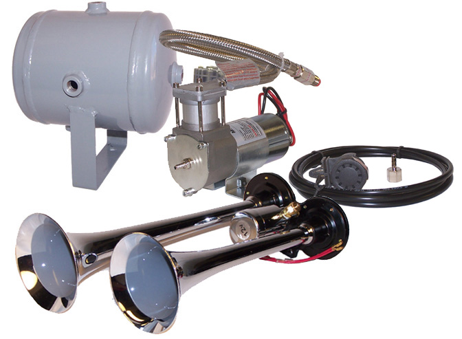
Recently, one of our customers wants to remote control his air horn in his truck. He needs a momentary remote that he can honk a “LOUD” horn located outside the toolbox in the box of his truck. It is a pneumatic horn that needs approximately 125PSI air. The air has to be momentarily transferred to the horn using a solenoid. The solenoid is controlled by applying 110volts. The 110 volts is obtained by the 3000watt inverter that is also inside of the toolbox in the box of the truck.

Our reply:

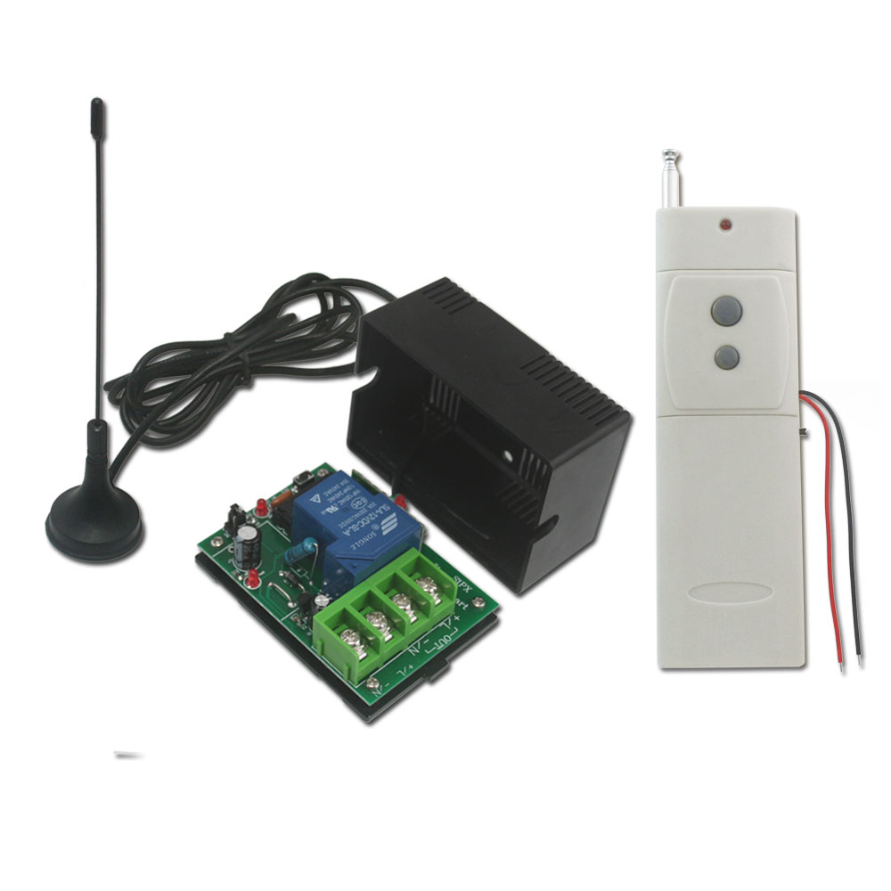
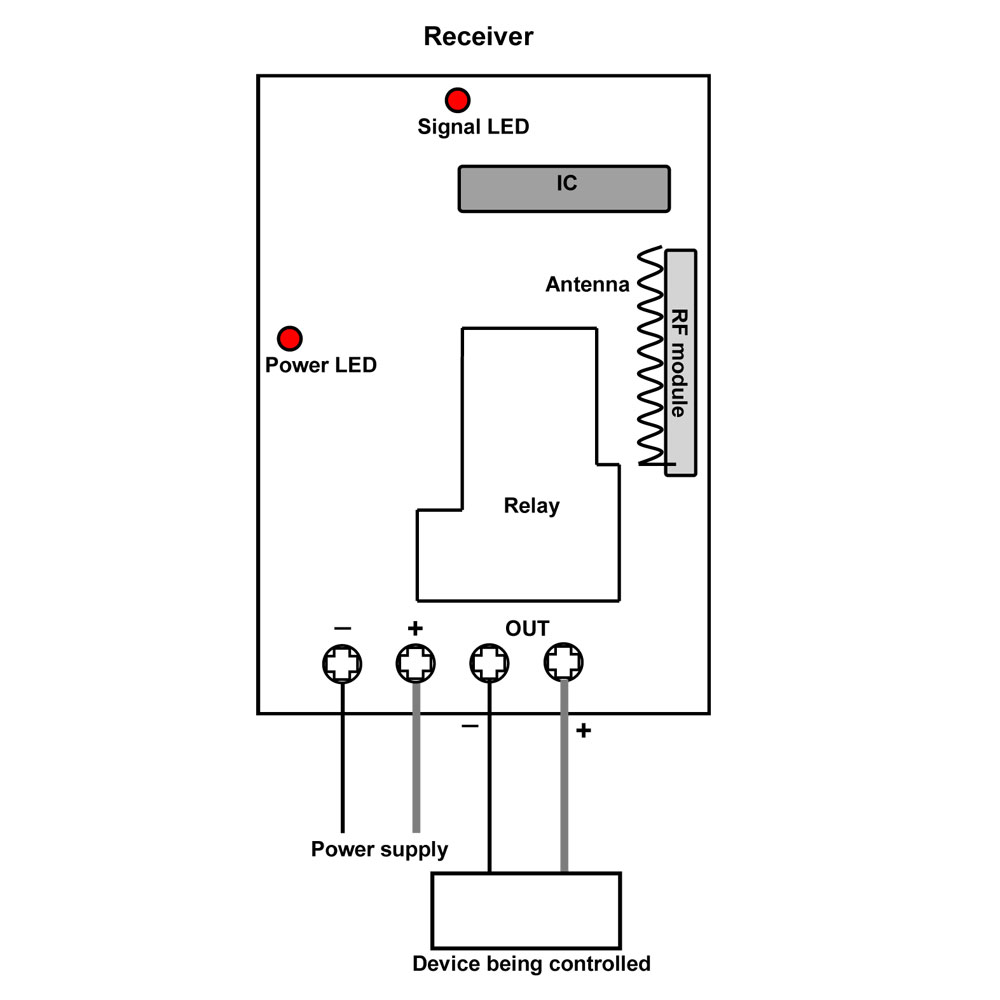
We recommend the remote receiver model of one channel ac direct power output and one button transmitter (S1X-AC220+C-1). The being controlled devices can get power supply from the receiver directly when the receiver is power on. The working current is 100V~240V.

The receiver will be mounted next to the solenoid inside the toolbox in the box of the truck. The transmitter can be mounted under the center post of the steering wheel (The transmitter is small enough for concealing).

He can honk the horn using a momentary working mode remote. When he press and hold the remote button, the solenoid will be open and air horn sends out extremely loud noise; When he release the remote button, the solenoid will be closed and air horn stops making a sound.

12-Channel Remote Control Pyrotechnics Ignition System Ignites Cascade Pyrotechnics

A new 12-channel remote control pyrotechnics ignition system has been added to our online store. It can ignite various kinds of electric fireworks directly, or cascade pyrotechnics which are used at stage. Remote control firework ignition reduces accidents like skin burn and accidental explosions.

12 channel firework ignition system

It contains 12-button remote transmitter and 12-channel ignitor. Each channel can ignite about 25 pyrotechnics simultaneously. It also has many features including test function, voltage indicator, waterproof case and manual operation mode. Wireless signal pass through walls, floors and doors. The remote control distance is 500m/1500ft (theoretically).

Let’s show you all how to use this remote control pyrotechnics ignition system.

First of all, we should prepare materials. We have firework ignitor and remote transmitter as well as cascade pyrotechnics.

S12PS1-ANT1&CB-12L material 2

Here comes to wiring. Wire cascade  pyrotechnics to the ignitor, the  pyrotechnics can be remotely controlled by remote transmitter from any place within a reliable distance.

S12PS1-ANT1&CB-12L wiring

Press button to ignite cascade pyrotechnics. The  pyrotechnics go off in a cascade of color.

S12PS1-ANT1&CB-12L firework ignition


How to Control Speed of Engine Rotation

Question from customer:

I need a control system for controlling a DC 12v engine, I seek to control the speed of rotation depending on the voltage applied.

Answer:

We recommend 2 channel motor speed remote controller—S2PFS-DC12 and CV-6-2.  By comparison with other motor remote controller, this controller S2PFS-DC can control speed of motor rotation. It won’t depend on the voltage applied because two speed control knobs on the receiver are to adjust the speed of two motors separately.  You can control two engines by one remote controller simultaneously. Maximum working current is 10A for each channel.

remote control model

You may be wondering how it works. Let’s show you how to control speed of two motor rotations.

1 x 2 channel dc remote control receiver (S2PFS-DC12)

1 x 6-button remote transmitter (CV-6-2)

1 x dc12v power adapters

2 x dc motors

S2PFS-material

Here comes the wiring.

Motor 1 is supposed to be connected to terminals A1&A2 at receiver. Motor 2 is supposed to be connected to terminals B1&B2 at receiver.

S2PFS-wiring-y 2

Speed Adjustable Operation

Besides ordinary starting and stopping operation, rotation for forward and reverse by transmitter, we mainly show that twist two knobs on the receiver to adjust the speed of rotation.

Knob 1 controls motor 1; Knob 2 controls motor 2.

For motor 2, twist the knob 2 anti-clockwise, the speed will be faster; twist the knob 2 clockwise, the speed will be slower.

S2PFS-DC+CV-6 motor2speed adjust COPY

For motor 1, twist the knob 1 clockwise, the speed will be slower; twist the knob 1 anti-clockwise, the speed will be faster.

S2PFS-DC+CV-6 motor1 speed adjust COPY


Wirelessly Romote Control Water Valve by Sprinkler Controller

Question from Customer:

I am trying to design and build a remote switch system for my sprinkler system. I need to use the sprinkler controller (12v output for on) to trigger a transmitter to switch a 12v operated valve on the other side of the yard (about 300m away.) I have mains power at both locations but the underground 12v wire from the controller has been damaged so I would like to build a remote system to save putting new conduit for around 300m across the yard.

Looking at your systems, the easy part would be the receiver end because I would only need a 12v power supply. The hard part will be getting the transmitter to switch on when the sprinkler controller switches on (12v).

sprinkler-controller

Answer:

We recommend direct power output high power long range remote control kit—S1PX-DC12-ANT2+CB-2V. The remarkable feature of this kit is that its transmitter is triggered DC power 5~28V input. That is to say, the transmitter will send out RF signal to receiver as long as it gets a 5~28V voltage from a device. Besides this advantage, its working distance is up to 2000m (6000ft). And the working current is 30amp. RF signal can pass through doors, walls and other obstacles.

remote control

Look at the following simulated diagram. The sprinkler control controls the valve box through the underground electrical wire initially. Unfortunately, the wire has been damaged. However, customer is unwilling to put new conduit for about 300m across the yard.

original wiring

So using our product to solve this problem is a wise choice. We connect the black wire of transmitter to the common wire of sprinkler controller; Connect the red wire of transmitter to wire from controller to valve. On the other hand, in the control valve box, valve common wire is supposed to be connected to the negative terminal of receiver; valve wire should be connected to the positive terminal of receiver. (As the following application circuit shown)

application circuit


Wiring modification

When you switch on sprinkler controller, the transmitter will be triggered by 12V voltage from sprinkler controller and sent out RF signal to indicate receiver to work. The valve is open and it starts the irrigation. Likewise, you switch off sprinkler controller, the triggered transmitter will indicate receiver to stop working. The valve is closed and it stops the irrigation.

There is no need to put new wire between sprinkler controller and valve control box. It is no longer the hardest part of getting transmitter to switch on when the sprinkler controller switches on.

irrigation 2

2-channel Wireless Remote Switch On and Off Light and Lock

One of our customers lives in large house in the countryside and enjoys a stretch of green field. Recently, he bought an adjustable time delay control kit from us because he wants to control his door lamp and lock beside the door. When he drives in and out, he can press button to open and close the door and even he can control lamp in the evening. (as the following picture shown)

This 2-channel wireless remote switch, which we provided, operates in time delay control mode. Adjustable delay time can be 0 second~99 hours. For its 2 channels, you can adjust delay time for two relays optionally according to your actual requirement. Our customer used it to turn on the lamp and open the door in the meantime.

We would like to show the simple procedure.

After preparing material, we do some wiring. Here is the wiring picture.

The remote control kit is installed on the wall. (The following is what customer did.)

The lamp and electric lock connect to normally open terminals B&C of relay 1 and relay 2 respectively. The customer adjusted delay time 1 minute for relay 1 and 30 seconds for relay 2. Button 1&3 controls relay 1; Button 2&4 controls relay 2. He drives in and out in the daytime, he can press button 1 to open the door. The door will close by itself after 30 seconds. Of course, he can press button 3 to close it immediately as soon as he goes out of the gate. In addition, lamp need to be turn on at night, he can press button 2 to turn on the lamp. And he can press button 4 to switch off the lamp at once or let it go out by itself.