1 Channel Momentary Controller Control Hydraulic Lift Up and Down

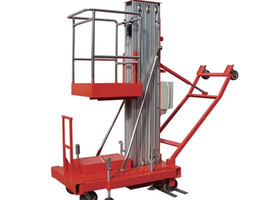
The hydraulic lift is a device used to lift or bring down loads from one floor to another in multi-storeyed buildings or stereo garage car lifting. The hydraulic lifts are used widely in cars, containers, mold making, timber processing and chemical filling for purpose of different working height need. Maybe you just want to use small-sized hydraulic lift platform to do something and just want it to be remote controlled so that it can bring you more convenience.

hydraulic lift

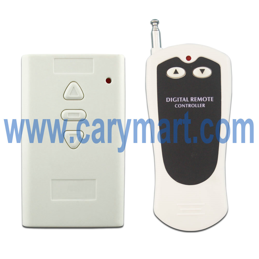
Here you can use 1 channel momentary controller (S1FM-AC220+CV-2-2) to remote control your hydraulic lift up and down.

This kind of controller has inversion control mode. It is 10 amps of its maximum current and 500m working distance. The operation is also very easy.

1_01

Connect live wire to terminal “L” and neutral wire to terminal “N”. Then connect AC motor to terminals “UP”, “COMMON” and “DOWN”. You can exchange “UP” and “DOWN” wires of motor to change the rotating direction of motor.

1_06

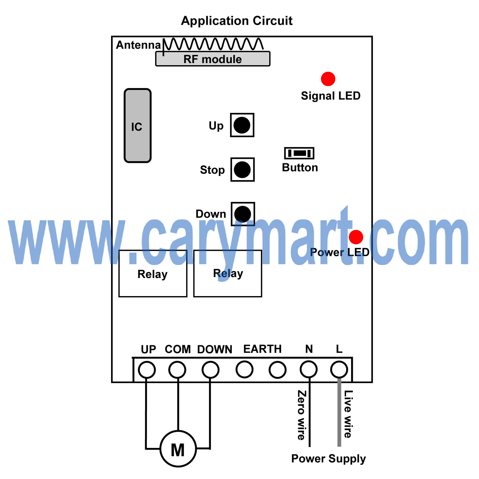
Press and hold button ▲ on remote or receiver: Terminals UP and COMMON directly output AC110V / AC220V; motor rotates continuously in positive direction.

Release button ▲ on remote or receiver: Stop the motor.

Press and hold button ▼ on remote or receiver: Terminals DOWN and COMMON directly output AC110V / AC220V; motor rotates continuously in reversal direction.

Release button ▼ on remote or receiver: Stop the motor.

Code Learning and Deleting

This is the digital display tube circuit board with fixed time controlling function. There are 12VDC power input and output terminals, manual switch, digital tube for time and jumper.

digital tube circuit board

There are also several buttons and terminals at circuit board. S1 (SET), S2 (+), S3(-), S4(LEARNING BUTTON) from right to left.

setting button

There are 3 controlling methods in it. They are manual switch control function, remote control function and fixed time controlling function. First of all, we will introduce the code learning and manual switch control function.

Code Learning:

1) Press button S4; signal LED on the controller keeps shining. The controller enters into status of LEARNING.

2) Press any one button on remote control. If signal LED flashes quickly 5 times and turns off, it means learning is successful.

3) When controller is in the status of LEARNING, press again button S4, signal LED turns off, learning process will be discontinued.

4) The controller can learn several remote controls with different codes.

We can test the learning situation, press “▲”, motor rotates in positive direction. Press “■”, stop the motor.

Code Deleting:

If you don’t want the controller to work with the remote control when you have learned remote control to the controller, you can delete all codes of remote controls, which are stored in the controller.

Operation: Press and hold S4 until signal LED flashes slowly; release the button, LED keeps slow flash. We can test the code deleting situation, press any buttons of transmitter, there is no response from motor. That means all stored codes have been deleted successfully.

Here is code learning and deleting videos for your reference.

DC Motor Rotates Automatically Via Temperature Variation

Our new digital tube circuit board has outstand feature which can remote control motor on and off through temperature variation around. We have introduced how to preset temperature figures in it previously. Next, we’d like to introduce how to control motor via temperature variation.

IMG_2253-1

When the actual temperature is higher the high temperature, motor rotates in positive direction; when the actual temperature is lower the low temperature, motor rotates in reverse direction. You need to press remote or manual switch to stop the motor.

We have preset designated highest temperature 45℃ and designated lowest temperature 25℃. Here we see the operation procedure.

At first, the actual temperature around is lower than preset low temperature 25℃, motor rotates in reverse direction.

picture 1

At this time, if we want to stop the motor, we can heat the temperature sensor with hair dryer. When the actual temperature around the sensor is higher than preset low temperature 25℃, we press “■” on the transmitter to stop motor. Otherwise, we cannot stop motor because the temperature around cannot reach above 25℃ in winter at our end.

picture 2

Continue to heat the temperature sensor. When actual temperature around the senor is higher than preset high temperature 45℃, motor rotates in positive direction.

picture 3

At this time, if we want to stop the motor, we should wait that the actual temperature around the sensor is lower than preset high temperature 45℃, you can press “■” on the transmitter to stop motor. Otherwise, when the temperature drops lower than 25℃, it begins to reverse rotation.

picture 4

After a while, When actual temperature around the sensor drops lower than preset low temperature 25℃, motor will still rotate in reverse direction.

picture 5

At this time, we must heat temperature sensor makes actual temperature around sensor higher than preset low temperature 25℃, we press “■” on the transmitter to stop motor.

picture 6

You can follow my example of video.

How to Set Temperature Data for Digital Tube Circuit Board

The significant feature of digital tube circuit board is temperature variation remote controlling. That is to say, it can preset designated temperature data, and device which is connected to this controller will is activated when it reaches the designated temperature. There is a temperature sensor installing in that board.

IMG_2253-1

We will like to introduce how to set temperature data for circuit board.

Press and hold S1 (about 2 seconds) to enter into automatic working setting. Digital tube display “A40”, at this time, you can set the high temperature 45℃, then, press S2(+) or S3(-) to adjust according to your need. Press and hold S1 (about 2 seconds) to save data and log out automatically. Press S1 again, Digital tube display “b20”, at this time, you can set the low temperature 25℃, then, press S2(+) or S3(-) to adjust according to your need. Press and hold S1 (about 2 seconds) to save data and log out automatically. The correspondent data will flash when we are setting.

You can follow my example of video.

Customized Digital Circuit Board Remote Control DC Motor

This digital tube circuit features in manual control and remote control. There are two working modes in it. We will switch modes through inserting or not inserting pin to jumper. From right side to left side of this board, they are power input terminals, power output terminals, four buttons: (SET), S2(+), S3(-), S4(LEARNING BUTTON) for setting or adjusting, manual switch jumper, pin jumper.

IMG_2251-1

This is board can be a reversing controller, with forward-reverse-stop capability. You can rotate the motor in positive or reversal direction with the transmitter (remote control) from any place within a reliable distance, wireless rf signal can pass through walls, floors and doors. But now only DC power is available. It is suitable for the motors of blind, rolling door, projection screen, awning, winch or other appliances and mechanicals.

Just wire DC motor to Output terminals of circuit board and supply power to circuit board.

Insert pin to jumper: Press and hold the “▲” button, motor rotate in positive rotation; release the “▲” button, motor stops. Press and hold the “▼” button, motor rotates in reverse direction; release the “▼” button, motor stops.

Do not insert pin to jumper: Press the “▲” button, motor rotate in positive rotation; press the “■” button, motor stops. Press the “▼” button, motor rotates in reverse direction; press the “■” button, motor stops.

The following video is for your reference.