1 Channel RF Remote Controller Switch AC Lamp Off/On

This is the one-to-many series remote controller. The 1 channel rf receiver is normally open &closed contact, you can wire lights, motors, fans, electrically operated doors / locks / windows / blinds / cars or other appliances with AC 110~240V or DC 0~28V. The transmitter is 12-button and its transmitter is 500m/1500ft. That transmitter can remote control 12 lamps at most when it pairs up with 12 receivers. Here you will see an example to remote control one ac lamp with this kind of remote controller.

Here is the material.

material

Next step is the wiring.

wiring

Setting control mode Latched: Do not connect Jumper-1 and Jumper-2

Press button 1, turn on lamp.

button 1 light on

Press other button, turn off lamp.

button 2 light off

Video

Hobby Project Motors Remote Controlling

Overview:

I want to control 6 different small electric DC motors for a hobby project.

Solution:

This 12 channel dc remote controller (S12CA-DC12+CV-12) can help you controls 6 dc motors’ positive and reverse rotation. The receiver works with a 12-button remote transmitter. It only can be used to control 6 motors for every two relays in the receiver can control one motor to rotate in forward and reverse other than controlling at most 12 same or different off/on electric devices. Remote distance is up to 500m.

12-channel-remote-control

Look at the following wiring diagram and picture. The wiring is just a little complicated. B is common contact. Each motor should be connected to B terminals of every two relays. A is normally closed contact and C is normally open contact. Connect contact C to the positive and connect contact A to the negative. We connect motors one by one.

application-circuit

S12CA-DC&CV-12 Wiring

Operation:

There are more than one working modes of that controller. Generally speaking, you will choose the momentary mode for motor controlling.

Learning Momentary control mode: When the receiver is in the status of LEARNING, press button 2 of the remote control.

Control mode Momentary (Channel 1~12): Press and hold -> On; Release -> Off.

Controlling motors at random just for an example from following demonstration:

If you want you control Motor 4:

Press and hold button 7, motor rotates in positive direction; Release button 7, motor 4 stops. Press and hold button 8, motor rotates in reverse direction; Release button 8, motor 4 stops.

S12CA-DC&CV-12 Motor 4

High amp Load Receiver and Wall-mounted Rocker Switch for Pump

Overview:

I want to remote control my submersible pump which draws water every day. It is 30amps and runs 220V power supply. Can you get the single channel remote control kit 30a ac 110V/220v with a wall mount remote control switch?

Solution:

We suggest that you can use 110V/220V power output high amp load receiver (S1PX-AC220) & wall mounted rocker switch. The receiver circuit is designed for high capacity device (30amps). It is 110V/220V power output, you don’t have to add additional power supply for your submersible pump which is to be controlled. You can only wire submersible pump to receiver “OUTPUT” terminals. When power for receiver is on, submersible pump will work. And when high amp load receiver works the wall mounted rocker switch, their working distance can reach 500m (theoretical data in the open field). You can use screws to install rocker switch to the wall.

remote-control-kit

Wire submersible pump to the L&N contact terminal of receiver, and power receiver on. Install rocker switch on the wall.

motor-wiring-diagramt

Press the rocker switch, submersible pump start to draw water.

Press the rocker switch again, submersible pump stop drawing water.

Motor Remote Controller and Contactor Remote Control Winch

Question from customer:

Hi, I am looking for a 110 volt remote control for a winch that pulls my boat from the water into my boat house.

Requirements:

120 volt

20 amps max

Momentary switches

Do you have a kit that meets these requirements?

Boat Electric Winch

Answer:

First, we’d like to recommend motor momentary remote controller (S1FM-AC220&CV-2-2). It can remote control motors of rolling blinds/ doors, projection screens, awnings, pumps, winches, conveyors or other electric appliances and machineries. With 2 directive buttons ▲(Positive rotation) and ▼(Reversal rotation), you can rotate the motor in the positive or reversal direction with the transmitter (remote control) from any place within a reliable distance(this kind of remote controller is 500m/1500ft). Power supply is AC 100~240V. But this maximum current is 10amps, it is not enough for you to remote control your 20amps winch. So we’d like show you contactor motor starter relay, you can use it amplify current which you need. AC contactor (aka motor starter) is a high capacity relay. It is often used to control a motor or as a main power switch. It’s used for long range connection and circuit disconnection, frequent activation and controlling AC motor.

11_04

Here is the wiring diagram. Two contactors will act as a bridge between remote controller and high power motor to help activate high power motor to rotate in positive and reversal position.

connection diagram

Wire A1 terminal of contactor 1 to UP terminal of receiver, and A1 terminal of contactor 2 to DOWN of receiver. Wire T2 terminals of contactors 1&2 to winch motor. Wire winch motor to COM terminal of receiver. Supply power to receiver and contactor 1&2 respectively.

Operation:

Press and hold button ▲ on remote: Motor rotates continuously in positive direction.

Release button ▲ on remote: Stop the motor.

Press and hold button ▼ on remote: Motor rotates continuously in reversal direction.

Release button▼ on remote: Stop the motor.

How to use One Device to Remote Control Another Device

Automation or automatic control is the use of various control systems for operating equipment as machinery, uses in factories, home. The biggest benefit of automation is that it saves labor, energy and material to improve quality, accuracy, efficiency and precision. Have you ever thought about home automation?

Someone wants to build home automation. Module 1 will connect to one existing device which make module 1 transmit RF signal to module 2 to indicate either “ON” state or “OFF” state. Module 2 will connect device which is ready to being controlled. When module receives the signal from module 1, it will turn on or off controlled device.

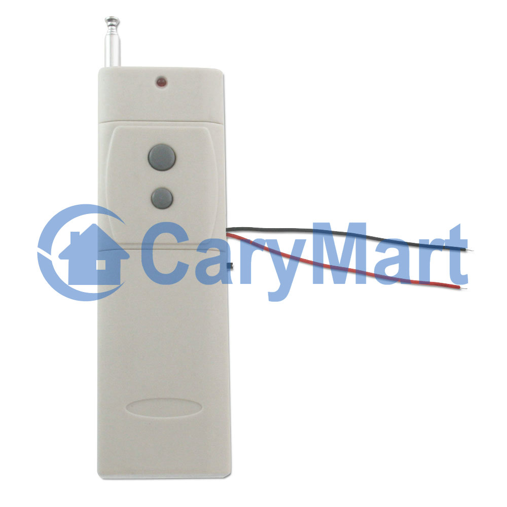
In fact, we have a completely new product 5~28V triggered great range transmitter of CB-2V which is applied for one device controlling another device. This transmitting module will be triggered by DC power 5~28V input. When your existing device is on, the transmitter will get power to send signal to receiver. We really hope this kind of remote can satisfy his needs.

voltage triggered transmitter

We think our product can meet his need. According to his requirement, that transmitter can work  with dc 6V 1 channel latched long range receiver model of (S1L-DC06-ANT2). The receiver needs low voltage and current. Working voltage range of relay can be DC 0~28V. And The existing device will supply low current to activate transmitter. They work together to finish the automation.

1 channel latched receiver

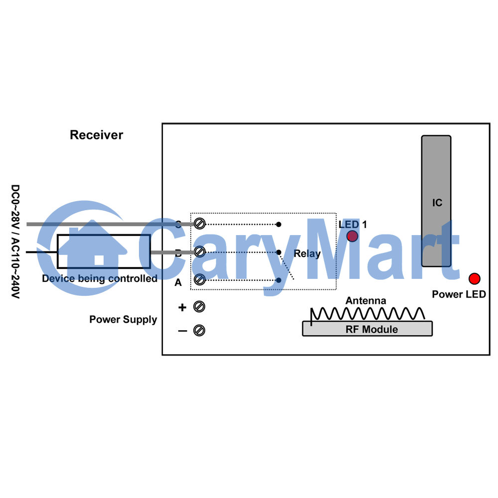
Let’s study the wiring diagram. That is fairly simple. Existing device is connected to the positive and negative terminals of the transmitter. The device being controlled is connected to the normally open terminals “B”&”C” of receiver.

transmitter diagram


receiver application circuit

Or our receiver is activated by DC6V power. If the device he wants to control is also activated by 6V. We provide another wiring diagram to you.

6V circuit

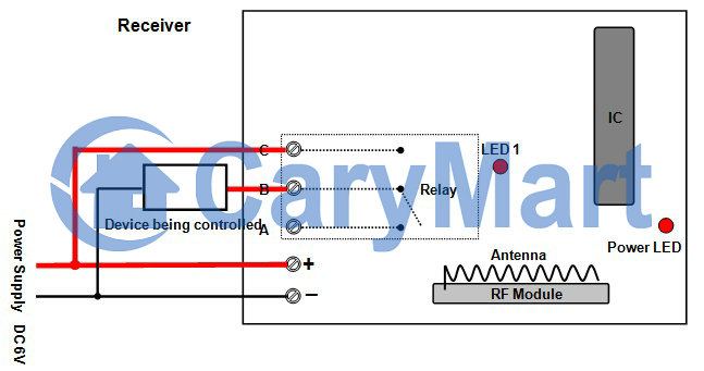
When the transmitter got a voltage input from the working existing device, the transmitter will be triggered and send an “On” RF signal to the receiver. When the receiver received this signal, it will indicate the device being controlled to “On” state. Likewise, the existing device stops working and transmitter will send an “Off” RF signal to receiver. After receiving the signal, the receiver will indicate the device being controlled to ‘Off” state.