How to design a wireless remote control outlet by yourself?

We use a simple RF remote kit to design a DIY wireless remote control outlet, so that we can simply connect a variety of electrical appliances to this outlet, and use the remote control to wirelessly control electrical appliances. Such as control lights, fans, motors, heaters and other appliances.

Introduce the wireless remote outlet DIY process is as follows:1

  1. The required components including: Ordinary wireless remote kit (1 x waterproof transmitter CWB-2 and 1 x receiver S1PX-AC), 1 x American plug power cord, 1 x American power outlet, 1 x waterproof case (100mm x 68mm x 50mm) and 2x PG9 waterproof connectors. This receiver S1PX-AC is AC power input and output, its maximum load is 15A. The maximum remote control distance for this wireless remote control kit is 50 meters, and the transmitter is waterproof. If you want control farther distance, you can use another wireless remote control kit (Model 0020059 (S1PX-AC-ANT3 & CB-1/CB-2).
  1. Test the transmitter and receiver to determine whether work:

2-1 First match between the transmitter and receiver, the operation is as follows:

1) Press the learning button of receiver for 1- 2 seconds; signal LED on the receiver is on. The receiver enters into status of LEARNING.

2) Press any one button on transmitter. If signal LED flashes quickly 15 times and turns off, it means learning is successful.

2-2 Test remote control function

Connect 120VAC power to the input terminals of the receiver and use the voltmeter to measure the receiver output terminals.

When pressing the button A on the remote control, the voltmeter shows the voltage is 120V.

When pressing the button B on the remote control, the voltmeter shows the voltage is 0V.

  1. Drill two holes 15MM in diameter on the waterproof shell, as shown:3
  2. Peel off the power cord from the middle of the American plug and separate these three wires, which are live wire, neutral wire, and earth wire. As shown:4
  3. Fixed circuit board in the waterproof shell, and fitted with two waterproof connectors.
  4. Install the American plug power cord:

Cut the live and neutral wires of the American plug power cord from the middle.

Connect one end of the live wire to to the input terminal “L / +” of the receiver, and connect the other end of the live wire to the output terminal “L / +” of the receiver.

Connect one end of the neutral wire to the input terminal “N / -” of the receiver, and connect the other end of the neutral wire to the output terminal “N / -” of the receiver.6

  1. Install the American outlet: Connect the output of the power cord to American7
  2. Close the lid. DIY wireless remote outlet installation is completed.9
  3. Test: Plug a AC fan into its outlet, then plug the outlet into 120VAC power and turn on the fan switch. The fan works when button A on the transmitter is pressed; and the fan stops working when button B on the transmitter is pressed.

In addition, we also sell other models of wireless remote control outlet. Such as the British wireless remote control outlet (model 0020712), European wireless remote control outlet (model 0020716), European waterproof wireless remote control outlet (Model 0020718), American wireless remote control outlet (Model 0020714). For product information available online shop search, more information, please visit Carymart.com.


How to use a dry contact to wirelessly trigger the flash LED alarm horn?

In general, RF wireless control systems use a remote control or a transmitter to control the device that connected to a wireless receiver. However, in some special applications, we need to use of a dry contact (normally open / normally closed contact) to remotely trigger or control another device in the distance.

One of our clients owns a shop. In the daily operation, it is necessary to maintain public safety, so he installed a security alarm system in his shop, equipped with wireless magnetic detectors, wireless infrared detectors and wireless fire detector. When these detectors are triggered, the warning horn that connects to the warning system will sound the alarm at the same time. After the shop is closed in the evening, he usually will go home and enjoy the rest time. The shop is about 800 meters away from his home. In case there is any unexpected situation in the shop, such as breaking into a thief or a fire alarm, the warning horn in the shop will be triggered. But because the shop was too far from his home, he could not hear the alarm sound, which would delay the best time to take remedial action. So, the client contacted us, also told us about his worry. He wanted us to figure out a wireless solution to install a wireless system. The reason is that he paved a line from the shop to the home is not realistic, and he would like to install an warning horn at home, when the shop warning host is triggered, the home warning horn will ring simultaneously. He told us that his alarm host had a normally open contact output. When the alarm host was triggered, the normally open contact output would be closed.

We recommend a normally open contact wireless trigger alarm system (model 0050001) based on the client’s situation. The system includes a transmitter CB-2N (model 0021045), a wireless receiver S1X-DC12-ANT3 (model 0020490), a flashing LED Alarm Siren (model 0040027) and a DC 12V power adapter (model 0010124). The transmitter CB-2N is a normally open dry contact trigger type, which has two input lines, and the two lines are usually disconnected. When connecting these two lines, the transmitter is triggered and a radio control signal “ON” is transmitted. However, when these two lines are disconnected, the transmitter is also triggered and another radio control signal “OFF” is transmitted. The receiver S1X-DC12-ANT3 is a DC 12V input / output type with a maximum operating current of 10A and has a waterproof case and an external telescopic antenna that can be installed outdoors for use. When this receiver S1X-DC12-ANT3 is triggered, it will output DC 12V power. This flashing LED Alarm Siren works at 12V DC power supply. When it is connected to the DC 12V power adapter, it will sound an alarm and flash at the same time, and the volume of the warning sound is also adjustable. This normally open contact wireless trigger warning system in the open area can be achieved as far as 1000 meters working distance.

The example diagram and specific operation of wireless remote control warning system are as follows:

The client first connects the normally open contact of his alarm host to two input lines of the transmitter CB-2N, then connects the DC 12V power adapter to the wireless receiver S1X-DC12-ANT3, and connects the alarm light to the output of this receiver. When any detector in the shop is triggered, the alarm host is triggered and the normally open contact output are closed. The transmitter CB-2N is triggered simultaneously and transmits an “ON” wireless signal to the receiver in the far range. When the receiver S1X-DC12-ANT3 receives this wireless signal, it outputs a DC 12V power to turn on the flashing LED Alarm Siren. When the alarm host lift the alarm state, then the normally open contact output will be disconnected. The transmitter is triggered again and an “OFF” wireless signal is transmitted to the receiver in the distance. When the receiver S1X-DC12-ANT3 receives this wireless signal, it will stop outputting 12V power and the alarm light will be turned off at the same time.

This type of RF wireless control system consists of a transmitter and a receiver. Transmitter can be used to connect a variety of devices with normally open / closed contact output, such as warning host, cable detectors, various sensors, limit switches, PLC programmable controllers (Programmable Logic Controller) and so on. The receiver can be connected to a variety of DC / AC equipments, such as alarm speakers, lights, pumps, motors, electric doors and so on. Normally open contact wireless remote control kit mainly utilizes one device with normally open / normally closed contact output to wirelessly control another AC or DC device. It can be used in many industries such as reservoir level control, automatic remote control of industrial equipment, simultaneous remote control of agricultural equipment, and the like.

In the online shop Carymart, we have two types of transmitters, which are CB-2N (Model 0021045) and CB-2N-2 (Model 0021046). We have three types of receivers. 1. DC power output receiver, such as receivers S1X-DC12-ANT3 (model 0020490) and S1PX-DC12-ANT2 (model 0020438), they are commonly used to control DC equipment. 2. AC power output receivers, such as receivers S1X-AC220-ANT3 (Model 0020393) and S1PX-AC220-ANT2 (Model 0020442), they are commonly used to control AC equipment. 3. Relays (NO / NC) Output receivers, such as receivers S1U-DC12-ANT2 (Model 0020249), S1U-AC220-ANT3 (Model 0020466), S1PU-DC12-ANT3 (Model 0020302), and S1PU-AC220-ANT3 (Model 0020488). These relay type receivers act as a single-pole double-throw switch, and its relay output has three output terminals (normally closed, normally open, and common) that can be used to control various DC / AC equipments.

Transmitter CB-2N has two input lines; the working principle is as follows:

  1. When two input lines are connected, the transmitter automatically transmits an “ON” wireless signal, equivalent to the function of the button “ON” on the transmitter.
  2. When two input lines are disconnected, the transmitter automatically transmits an “OFF” wireless signal, equivalent to the function of the button “OFF” on the transmitter.
  3. When the receiver receives this “ON” or “OFF” wireless signal, it will drive its relay to turn on / off the connected device.

Transmitter CB-2N-2 has three input lines; the working principle is as follows:

  1. When the input lines 1 and 3 are connected, the transmitter automatically transmits an “ON” wireless signal, equivalent to the function of the button “ON” on the transmitter.
  2. When the input lines 2 and 3 are connected, the transmitter automatically transmits an “OFF” wireless signal, equivalent to the function of the button “OFF” on the transmitter.
  3. When the receiver receives this “ON” or “OFF” wireless signal, it will drive its relay to turn on / off the connected device.

Notice: The operating voltage of the transmitter is DC9V, and it can work for about 3 days with a model 6F22 9V battery. If the device has to work long term, we recommend using a DC9V power adapter.

How to use a device to remote control another one?

Customized wireless control solutions have always been our key service to meet our customers’ needs, especially for those unfamiliar with wireless control equipment products, we provide optimized solutions. For more information, please visit Carymart online shop.

We have a client who has an airstrip with AC220V runway lighting on the runway and a DC12V solar windsock light. The runway lights are 1000 meters away from the customer’s building and the solar lights are 150 meters away from the runway lights. When the plane lands, he needs to turn on both the runway lights and the solar windsock light at the same time.

The runway light is turned on / off by a manual switch from the building, however, he needs to walk up to the solar windsock light at 1000 meters to turn on the solar windsock light. For ease of operation, the windsock light is set from dusk to dawn has been open. But one of his neighbors complained that the windsock light have been lit to disturb the lives of them. So he told us the details of the situation by mail description clearly and wanted a wireless control solution to solve this problem. He demanded that he didn’t want to connect a control line from the solar windsock light to the building because it was 1000M away, the wiring was too cumbersome and the cost was too high. He wanted to install a wireless control system between the runway lights and the solar windsock lights so that they could operate simultaneously. In other words, when the runway lights are turned on, the solar lights are automatically turned on at the same time. When the runway lights are turned off, the solar windsock lights are also automatically shut down at the same time.

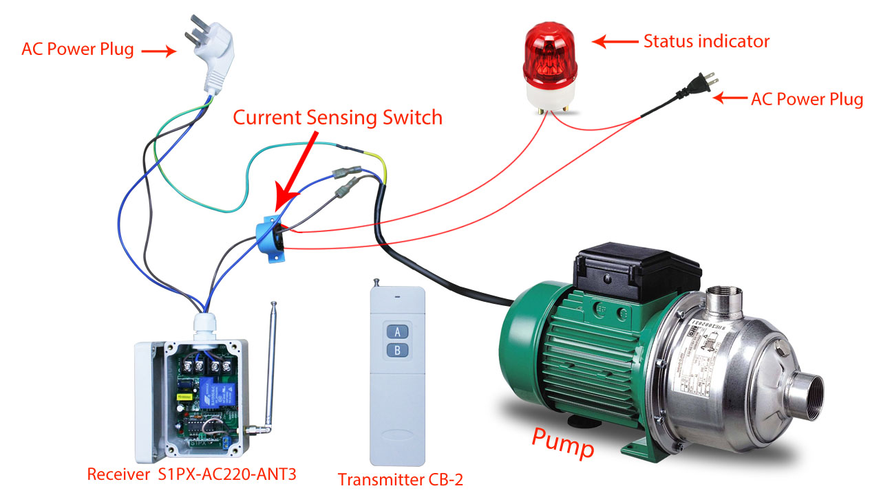
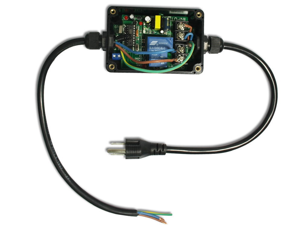
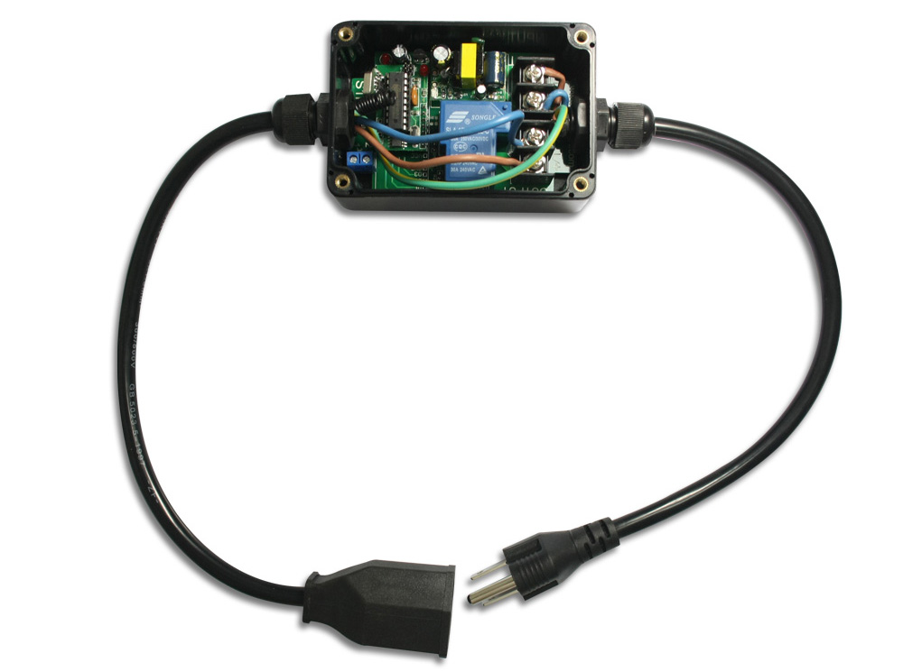
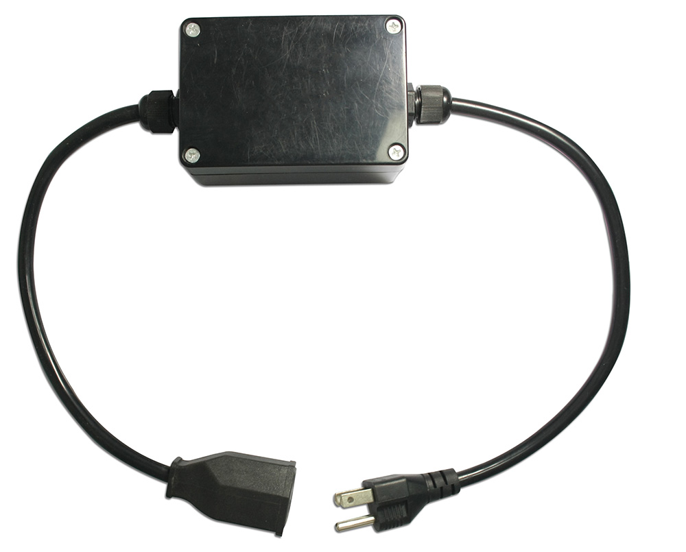
We recommend to customers based on the actual situation and customer requirements, a wireless lamp remote control equipment. The device includes a receiver S1X-DC12-ANT3 (model 0020490) and a transmitter CB-2V-AC (model 0021048). This transmitter is an ac power trigger type remote control, and it has two input lines. When an ac voltage is input, the transmitter is triggered and a radio control signal “on” is transmitted. When AC voltage stops input, the transmitter is also triggered and a wireless control signal “OFF” is transmitted. The receiver is DC 12V input / output type, the maximum operating current is 10A, and it has a waterproof case and external telescopic antenna, so it can be installed outdoors. This wireless light remote control device in the open area can be achieved as far as 1000 meters working distance. The user first connects the runway light’s AC220V power supply to the transmitter’s two input lines, and then the windsock light to the receiver’s output terminals.

The wireless light remote control device example picture and the specific operation are as follows:

When the user opens the runway light from the building, the transmitter (CB-2V-AC) detects that its two input lines have AC voltage inputs, then it transmits an “ON” wireless signal to the receiver. When the receiver (S1X-DC12-ANT3) received this wireless signal, it outputs a 12V power to turn on the windsock light. When the user turns off the runway lights from the building, the transmitter (CB-2V-AC) detects that the AC voltage has ceased to be input, then it transmits another “OFF” wireless signal to the receiver. When the receiver (S1X-DC12-ANT3) received this wireless signal, it stops the output 12V power, windsock light is turned off.

This type of wireless remote control device can use one AC or DC device to wirelessly control another AC or DC device, and it can be used in many applications, such as lighting control of a port or a dock, remote control of industrial equipment, remote control offshore platform or onboard equipments.

Nowadays, the world is facing the problem of power shortage. Street lighting and guiding lights are indispensable facilities in daily life, and we put forward higher requirements on the energy saving of street lighting. Traditional street lamp control methods include manual control, automatic clock control, light induction control, SMS control, etc., but those ways can’t achieve the control requirements under special conditions. Like during construction, when a device is turned on, automatically turn on street lighting in order to effectively use lighting to avoid waste. Therefore, the radio frequency remote control system can be integrated with the management of street lighting, which is to achieve high-performance automated, intelligent lighting management, and reduce operational and maintenance costs.

The radio frequency wireless control system is composed of transmitter and receiver. There are two types of transmitters. 1. DC power (DC5V ~ 28V) trigger type, such as the transmitter CB-2V (model 0021044); 2. AC power (AC100 ~ 240V) trigger type, such as the transmitter CB-2V-AC (model 0021048). Both transmitters can work with different receivers. And there are three types of receivers. 1. DC power output type, such as the receivers S1X-DC (model 0020423) or S1PX-DC (0020436), they are usually used to control DC equipment; 2. AC power output type, such as the receivers S1X-AC (model 0020391) or S1PX-AC (model 0020440), they are usually used to control AC equipment; 3. The relay output type, such as the receivers S1L-DC (model 0020042), S1U-AC (model 0020330), S1PU-DC (model 0020046) or S1PU-AC (model 0020275). It is equivalent to a single-pole double-throw switch with a relay output, and the relay has three output terminals, normally closed, normally open and common terminal. These receivers are usually used to control various DC / AC equipments.

Users choose different transmitter and receiver for different combinations, and it can achieve different control methods. 1. Use one AC device to wirelessly control another AC device. 2. Use one DC device to wirelessly control another DC device. 3. Use one AC device to wirelessly control another DC device. 4. Use one DC device to wirelessly control another AC device, etc.

The working principle:

When the transmitter detects a DC or AC power trigger signal, it automatically emits an “ON” wireless signal, which is equivalent to the function of the button “ON” on the transmitter. When this power trigger signal is turned off or the power trigger signal is stopped, the transmitter automatically transmits another “OFF” wireless signal, which is equivalent to the function of the button “OFF” on the transmitter. When the receiver receives the “ON” or “OFF” wireless signal that will drive its relay to turn the connected device on or off.

Notice: The operating voltage of the transmitter is DC9V, and it can work for about 3 days with a model 6F22 9V battery. If the device has to work long term, we recommend using a DC9V power adapter.

How to remote control and monitor ac pump?

With the increasing progress of science and technology, people require the electronic appliance with more automation and intelligence. Now, intelligent control system is adopting wireless remote control technique instead of traditional wire control technique, which can avoid the problems caused by wiring and adding new devices. In order to make the function of the wireless remote control traditional device isn’t limited by distance and space. It’s a more convenient method to be compare with traditional wire control.

Wired control technology:

Wired control technology is a relatively primitive technology. It adopts the pattern of integrated wiring, used in household, agriculture, industry, equipment erection, such as security systems, lighting control, heating, air conditioning, water control, etc., This technology is connected directly to the device through wire connections to achieve a single control or integrated application control function.

Disadvantages:

  1. It is necessary to install a large number of wires, the installation method is complicated, and the wiring cost is too high.
  2. The control panel of operation is fixed, so it is not convenient to use and can’t be freely controlled in any space.

Wireless control technology:

Radio frequency wireless control technology is a novel technology. People first simply connect controlled devices to wireless receivers by a simple wired connection, then achieve the wireless control function of connected devices through the transmitters or remote control.

Advantage:

  1. Simple installation, no need to install a large number of wires, the cost is greatly reduced.
  2. Portable remote control can be carried out in any reliable range for wireless control and convenient operation.
  3. Wireless control technology can achieve wireless control at a considerable distance, such as 1000M or further.

The wireless control system consists of a transmitter or remote control and a receiver. The transmitter or the remote control is made up of the keys, the coding circuit, the modulation circuit, the signal amplifying circuit and the antenna. Working principle of the Transmitter: The transmitter generates a specific signal when the button is pressed. Then this signal is processed by the modulation circuit, coding circuit and high-frequency amplifier circuit. Eventually it generates a radio wave, and this radio wave is emitted by the antenna. The receiver is made up of receiving antennas, RF receiving modules, decoding circuits, driving circuits and relays, and driving circuits and relays must be connected to the controlled devices. Working principle of the receiver: When the transmitter sends a RF wireless signal, the receiver receives this RF wireless signal through the antenna of the RF module, and then the wireless signal is analyzed and determined by the decoding circuit. Finally, according to the specific information of this RF wireless signal, the connected devices can be operated accordingly by driving circuit and relays. For example, a variety of lighting on / off, the door open / closed, the pump on / off operation, the motor forward and reverse control, air conditioning heating or ventilation system control, linear actuators telescopic control, vehicle equipment Wireless control, automation control of agricultural greenhouses, or other industrial equipment movement control and so on.

As we know, Radio frequency signals are transmitted through the media, generally the media is air. There are mainly three factors affecting the working distance of an RF wireless system. One is the receiver’s sensitivity of receiving wireless signals, and the other is the transmitter’s transmit power. The last one is the obstacles between the transmitter and the receiver. Suppose there are some obstacles in the propagation path, such as walls, high buildings, trees, cars, etc. These obstacles will seriously reduce the wireless transmission distance of radio frequency signals. For this reason, we propose two options to solve the problem.

  1. Replace the high-power remote control, ex. the working distance of normal CWB type waterproof remote control is only 50 meters, but the CP type remote control can reach 500 meters, and CB type remote control can reach further 1000 meters.
  2. Replacing the receiver’s RF antenna, using an external antenna with higher receiving sensitivity, such as external telescopic antenna or external magnetic sucker antenna.

One of our customers purchased a wireless remote control device from Carymart online shop, and successfully erected an AC water pump wireless control system, with a control distance of 1000 meters. The wireless pump remote control system includes a receiver (model:S1PX- AC220-ANT3) and a transmitter (model CB-2). This receiver is the ac power output type, and the maximum working current is 30A, it has the waterproof shell and the external telescopic antenna, which can be installed in the outdoor use. However, in practical application, the client encountered another problem that he cannot confirm the working condition of the AC pump from such a long distance through visual and auditory sense. When he presses the button of the remote and opens the ac pump through the receiver, the pump is working, but he can’t confirm the state of the work. Because he couldn’t see the pump, he worried the wireless signal was disturbed by other factors, so that the water pump could not be opened properly. Based on this situation, we have developed a visual status solution. Install a current sensing switch (model 0025011) on the AC pump, then install an indicator light (model 0040026) at the height position. The customer can confirm the working status of the AC pump by observing this indicator light. Working principle of the Current sensing switch: When it detects the current of the wire passing through its inspection hole, it will close its internal contacts and turn on the status indicator.

Their connection diagram and installation diagram as shown below:

 无线遥控抽水马达文章配图

The specific operation of wireless water pump remote control equipment with status indicator are as follows:

When the customer is within reliable control, he first presses the button A on the remote control CB-2. If the receiver normally receives this wireless signal, it will turn on the water pump. At the same time, the status indicator light installed at the top will also be turned on. So the customer can see the status lights in the distance, and confirm the pump is working properly. When the customer presses the button B on the remote to turn off the pump if the receiver normally receives the wireless signal. At the same time, the state indicator light will be extinguished, and the customer can confirm that the pump is in a state of suspended operation.

Such a wireless remote control device can also be equally applied to agricultural long-distance irrigation, household water storage wireless control, garden watering remote control, long-distance control of industrial equipments, remote control offshore platform or onboard equipments.

Using special transmitter to remote control everything

Transmitter (CB-2V) can be used to remote control garage doors, motorcycles, car alarm products, home security products, wireless remote control products, industrial control products, etc. The working distance of this kind of transmitter is 1000m / 3000ft in an open area. Compare with other transmitters, transmitter (CB-2V) has extended input wires. When it has DC 5~28V power input for red wire and black wire of the transmitter, the transmitter will be triggered and then it will send an RF signal of “ON” to turn on the receiver, the device controlled by the receiver will starts to work. When it does not have DC 5~28V power input for red wire and black wire of the transmitter, the transmitter will be triggered and then it will send an RF signal of “OFF” to turn off the receiver, the device controlled by the receiver will stops working.

Some typical cases:

The following are three typical cases that using transmitter (CB-2V) to remote control DC and AC equipments.

  1. Using transmitter (CB-2V) to remote control pump start relay.

One of our customers is trying to operate a pump start relay using an RF signal, but using an irrigation timer as the control for the transmitter instead of a fob or push button RC control. The irrigation timer has an output for wire controlled pump start relays. It is a simple 2 wire control, and is 24v output. There is also 110v output if needed, (to power the transmitter for instance.) He needs a transmitter that can be operated by the irrigation control using the 24v output to activate the transmitter. The irrigation control is approximately 200 yards from the pump start relay, and there is no clear line of sight.

images

t-1030-d-461e05db

Recommended product:

Receiver: Model: 0020488 (S1PUA-AC220-ANT2)

receiver

Transmitter: Model: 0021044 (CB-2V)

1

The reason why we recommend this RF remote control kit:

  1. According to the description from the customer, we know that the working range of his irrigation control is approximately 200 yards from the pump start relay. Theoretically speaking, the working range of this remote control kit which we have recommended to him can reach 2000M / 6000ft.
  2. The receiver 0020488 (S1PUA-AC220-ANT2) can control equipment with AC110~240V or DC0~28V, such as, pump, lights, motors, fans, electrically operated doors/ locks/ windows/ blinds/ cars and so on. The maximum working current of the receiver is 30A.
  3. The transmitter 0021044 (CB-2V) has extended input wires. When it has DC 5~28V power input for red wire and black wire of the transmitter, the transmitter will be triggered and then it will send an RF signal of “ON” to turn on the receiver, the device controlled by the receiver will starts to work. When it does not have DC 5~28V power input for red wire and black wire of the transmitter, the transmitter will be triggered and then it will send an RF signal of “OFF” to turn off the receiver, the device controlled by the receiver will stops working.
  4. Therefore, when wiring the customer’s irrigation timer to the transmitter, it can easily remote control his pump start relay.

In this case, the customer just needs to connect the power from irrigation control to the transmitter CB-2V, and connect the receiver S1PUA-AC220-ANT2 to the pump start relay.


  1. Remote control fluorescent light fixture.

Here is the customer’s question.

I’m trying to accomplish the following: Want to turn on a fluorescent light fixture whenever the garage door opener light (120v) is on. Want to place a wireless transmitter at the door opener with auxiliary wires that would tie into the light circuit (120v) on the opener. When power is applied to the transmitter it would send wireless signal to receiver and it would then close contacts and turn on fluorescent fixture. The contacts on the receiver would open when power (120v) is removed from the transmitter. I saw a similar posting on your website, but the transmitter (CB-2V) auxiliary wires do not appear to work with 120v. Could you please provide a solution?

genie-garage-door-opener-troubleshooting

The operation of this case is very simple. Just needs to connect the power from garage door opener to the transmitter CB-2V, and connect the receiver to the fluorescent light fixture.

  1. Remote control LED light on customer’s car roof and car’s packing light at the same time

This customer wants to remote control LED light on his car roof. He needs one transmitter and two very small receivers, He said that when the parking lights is on, the LED lights on the car roof should also turn on at the same time. The LED light should turn off, when the parking lights is off.

无标题

In this case, we recommend the customer to choose the transmitter CB-2V and the receiver S1XL-DC12. The customer just needs to connect the power from parking lights to the transmitter CB-2V, and connect the receiver S1XL-DC12 to the LED light. It’s done.

Operation:

We can show you how to use transmitter (CB-2V) to remote control small water pump.

As I have mentioned above, the most significance feature of transmitter (CB-2V) is that it has extended input wires, which means you can wire power supply to the transmitter and then switch on the power to remote control the water pump instead of pressing button of the transmitter to remote control the water pump.

First, let’s see what we need to prepare in order to achieve this action.

连线2

Material Preparation:

Receiver: 0020275(S1PU-AC220)

Transmitter: 0021044(CB-2V)

Some lines

Small water pump

Two water pipes

One AC Power Supply and two DC Power Supplies

Operation:

First, wire the DC power supply to the small water pump and terminal B of the receiver.

Then, wire the small water pump to terminal A of the receiver.

Next, wire the AC power supply to the receiver.

At Last, wire another DC power supply to the transmitter.

Now, all you need to do is switch on the power, and then you can remote control the water pump.

If you want to remote control the water pump by pressing the button on the transmitter, you will no longer need to wire the power supply to the transmitter. The following are the materials you should prepare.

连线1

These two operations can all remote control the small water pump, the water will move from the green bowl to the white bowl.

More information please visit our online shop: http://www.carymart.com/.