Alarm frequency : 433Mhz or 868Mhz?

smart-alarm-security

Among the technical characteristics that are regularly put forward by alarm dealers, frequencies are a recurring argument.

In order to better understand the ins and outs of the transmission frequencies between the alarms and their peripherals, here is a short summary of the main radio frequencies used:

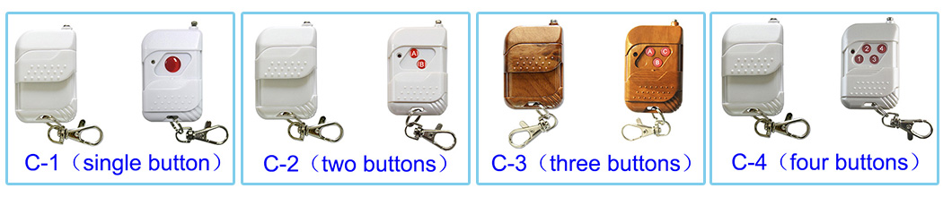
433 Mhz for wireless controls

433 MHz, this frequency is called free. Most wireless controls use it: remote control for garage door, roller shutter, light switch, wireless headset, TV remote control etc.

Due to its very common use, this frequency can suffer from congestion, i.e. interference and disturbances. However, the equipment transmitting on this frequency is limited in its transmission power and in fact there is no more reason for your alarm to be disturbed than your television or any other remote-controllable equipment.

One exception, however, is amateur radio. They use this frequency with powerful transmitters. Their emissions are able to disturb all the remote-controllable elements on the 433 MHz band. The number of French radio amateurs is however discretionary and most do not spend their days connected to their machines. If a cibiste were to interfere on the frequency of your alarm you would be warned well before by dysfunctions of the whole of the remote-controlled equipment of your residence. Apart from this case, which can be described as extremely rare, the 433 MHz transmitter and receiver therefore remains both effective and appropriate for the transmission of information.

This frequency has the advantage of offering an interesting range and a good penetration in buildings, in comparison with the band 868 Mhz whose signal attenuation is more important.

868 Mhz for alarms and security accessories

867.6 Mhz is strictly regulated and is dedicated to security equipment, i.e. alarm systems and their peripherals.

This frequency range, due to its height, offers a more attenuated signal than the 433 MHz band. The waves thus theoretically have a less good range because less penetration through buildings but this limitation is compensated by better antennas. The Effective Radiated Power (ERP) of a 433 MHz antenna is at most 10 mW. For an 868 MHz antenna the PAR can reach 500 mW. This amplification difference largely compensates for the native signal weakness.

Encryption security: One of the essential points of the radio communication of the alarm centres with their peripherals is the security of the transmitted data. To do this, the control panels use encryption to prevent hacking.

In a wireless alarm system, information is transmitted over several narrow bands and not on a single frequency. It is therefore technically very difficult to hack a current wireless home alarm system.

In conclusion after this theoretical approach it is important to know that these questions, if they have a purely technical interest, are not really fundamental in practice: according to my experience and that of various alarm professionals there is no fundamental difference in use.

One can therefore invest in an alarm emitting in 433 Mhz without making any error, the price difference of the 868 Mhz models is essentially based on the higher price of less common components.

Parking blocks, stop to thefts of places

There’s nothing more frustrating than going home after a hard day’s work or coming home from vacation to find your parking space occupied!!

A parking space is yours because it is allocated to you when you buy or rent an apartment.

The owners of the vehicles that park on your parking space are probably unaware that it is a reserved space, and that is why, in any case, installing a parking block or a parking arch (or barrier) clearly informs the driver of the undesirable vehicle that he does not have to park at this location.

remote control

Why equip yourself with a parking arch?

Practical and easy to use, a parking roll bar is a simple and effective way to reserve and secure your pitch.

Parking barriers are very popular best universal remote accessories for reserving parking spaces; they can be mechanical or automatic. There are several models exactly adapted to your needs.

Among the different barriers dedicated to parking areas we can mention the parking arches which are generally fixed to the ground by three supports, the parking posts which are made up of a single base, the parking blocks, the barriers, etc…

So, Carymart, barrier or parking block

Starting from a basic model, a parking arch with padlock closure is characterized as a folding and very resistant obstacle made of galvanized steel 32mm in diameter and as a perfect tool to ensure the availability of your parking space at any time. It is fixed to the ground and folds easily with a single movement held by the lock of a padlock. parking barrier

The ultimate is the automatic parking barrier. Ingenious and extremely comfortable, it allows you to reserve or free your parking space while remaining on board your vehicle thanks to its wireless remote control.

For safety, this parking barrier is equipped with a pressure and intensity sensor. When it is closing and encounters an obstacle (chassis, bumper, etc…) it goes back the other way (opening) in order not to create any damage to people and vehicles.

The pole or parking block is made of 3mm galvanized steel and its cast iron base has 4 anchors for better stability and solidity. It is a perfect deterrent and its reflective strips allow it to be seen from a distance.

rf remote

A few words to sum up

Retractable, foldable, autonomous or automatic, these protection and safety devices will make your life easier and softer since you will never have to worry about whether your seat is free at any time of the day.

The use of wired control and wireless control in combination

People make use of radio frequency wireless control technology, first, make a simple connection between the controlled equipment and the wireless receiver, and then use the transmitter to remote control the receiver, in order to achieve wireless control of the devices.
The wireless control system has the following advantages:
1. The installation is simple, no need to install a large number of wires, the overall cost is greatly reduced.
2. The operation is convenient. The user can carry on the wireless control of the equipment in any reliable range with the remote control.
3. To achieve remote control, wireless control can be implemented in a quite far range, such as 1000M or farther.

The wireless remote control technology brings convenience to mankind, but it also causes inconvenient.
1. When the user cannot find the remote control or the remote control is lost, the device cannot be controlled.
2. When the remote is lost, it takes the user to spend time buying new remote control and configuring it.

Assuming that people want to convert the original wired control circuit into a common wireless control system, the original circuit and manual switch need to be dismantled. But people usually want to retain the original wired control system (using manual switches to control devices), and want to add wireless control system (using the remote controller to control devices), so we need to use dual control mode. We combine the advantages of the wireless control system with the traditional wired control system to design a combination of wired control and wireless control. The solution uses a wireless receiver (with normally open and normally closed output), a remote control and a dual control switch (normally open and normally closed type), to achieve the dual control function of the device.

For example, the AC lamp’s wired control circuit, we can use this solution to increase the wireless control function, not only can switch the lamp by the manual switch but also can use the remote controller to turn on the lamp at the same time. The two functions are not affected by each other. As shown in the following chart, the cable control circuit of the AC lamp uses an ordinary manual switch to control the light. We implement this scheme by installing a wireless control system and a double controlled manual switch. The model of the wireless control system is 0020332 (S1U-AC220 & C-1). This receiver S1U-AC220 works on AC 100~240V power supply, which has a dry output with normally open and normally closed type (COM, NO, and NC). The transmitter C-1 is a single button radio frequency transmitter. The dual controlled manual switch also has a set of normally open and normally closed terminals (COM, NO, and NC).

The wireless control system in the open area working distance is up to 100 meters. If you want more control distance, you can use another 3000 meters wireless remote control products (Model 0020689 S1UW-AC-ANT3 & CC-1).

The circuit diagram is as follows:

The wiring diagram is as follows:

Wiring:
1) Connect the live wire of AC power supply to terminal “L / +” and terminal “B” of the receiver.
2) Connect the neutral wire of AC power supply to terminal “N / -” of the receiver and one side of AC lamp.
3) Connect terminal “L” of the double control switch to another side of AC lamp.
4) Connect terminal “C” of the receiver to terminal“L1” of the double control switch.
5) Connect terminal “A” of the receiver to terminal“L2” of the double control switch.

The operation is as follows:
1. Set the receiver’s working mode to auto-lock mode.
2. Match the remote control with the receiver. Please refer to the product specification.
3. The ways of opening/closing the lights:
a. Press the button on the remote control, the light is turned on; then press the button on the remote control, the light is closed.
b. Turn on the manual switch and the light is turned on; turn off the manual switch and the light is closed.
c. Press the button on the remote control, the light is turned on; then turn off the manual switch, the light is closed.
d. Turn on the manual switch and the light is turned on; then press the button on the remote control, the light is closed.

For this combination of wired control and wireless control, we offer different types of receivers to achieve dual control of different types of devices, such as all kinds of DC or AC devices. For more details of a variety of receivers, please visit our online shop CaryMart.

Wireless remote control crane

Wireless remote control technology has been very widely used. Whether it is satellites or household appliances mostly can be controlled by wireless remote control technology. RF control can fully liberate people from complicated manual labor, and wireless operates any electronic equipment at a distance as much as they want. The development of wireless remote control technology make people enable to enjoy the charm of science, also reduce labor intensity, improve labor productivity, and improve job safety. Crane is mainly used to load and unload objects, widely used in construction sites, commercial, factories, farms, supermarkets, and other occasions. Using wireless remote control technology can achieve crane wireless control. Crane wireless remote control system has the following advantages.

1. Reducing manpower costs. For cranes, truck cranes and other equipment, the operator can operate the equipment along with the wireless remote control technology, and no longer need the assistance of other people. Also, the single person can manage a number of cranes, so the operator is able to control the other equipment while manipulating the crane simultaneously.

2. Increasing the efficiency of operation. Because the operator can operate the equipment alone, it improves the accuracy and efficiency of the operation, avoids misunderstandings between the device operator and the ground commander, and applies to the precise installation operation such as equipment assembly.

3. Improve the environmental safety. When a worker operates equipment in toxic gas, high temperature, dusty and dangerous place, the operator can choose the environment that is suitable and safe to operate the equipment, the operator’s personal safety is protected, and the operation conditions have been improved.

Different types of cranes require different wireless control systems. When we use a wireless control system to control the single-phase crane, it is necessary to change the original control circuit of the single-phase crane. The scheme is simple and easy to do. For example, see Figure 1 below:

The single-phase crane is composed of a wired control handle, an emergency button, a limit switch, a fan, an AC motor (with a starting capacitor), a winch and a wire rope. The principle of the work is to use the forward and reverse rotation of the motor to drive the winch, and to make the wire rope be extended or retracted. The electrical schematic of this single phase crane is shown in Figure 2:

According to the electrical diagram of the wired control handle, we recommend a set of the wireless remote control system, the receiver model is 0020451 (S6C-AC220), the remote control model is 0021004 (C-3-2). The S6C-AC220 receiver in AC 100~240V power supply, it has 6 relay output (normally open and closed type), which has two kinds of control mode (momentary mode and interlock mode). The remote C-3-2 has three buttons (▲,▼,▇) with protective cover. The wireless control system can achieve the maximum distance of 100 meters in the open area. If you want to further control the distance, you can connect an external antenna to the receiver and use another high power remote controller, the model is 0021047 (CB-3-2).

The wireless remote control system installation process is as follows:

1. The receiver S6C-AC220 has 6 relay outputs. We need to change the receiver’s circuit so that the ▲ button of the remote control can simultaneously control the 3 relays on the left, and the ▼button can simultaneously control the 3 relays on the right. Circuit modification is shown in Figure 3 below :

2. We analyze the role of each line in the wired control handle, the wired control handle shown in Figure 4 below:

 Based on the analysis of the wired control handle and the crane electrical diagram, we know the function of all wires on the wired control handle, as shown in Figure 5 below.

 3. Use the receiver instead of the wired control handle, and the original wired control handle must be removed. The connection between the receiver and the motor is shown in Figure 6 below.

1. The receiver is set into a momentary mode, and the operation process is as follows: Press and hold the button ▲ on the transmitter: The relays 2, 4 and 6 are activated, the crane rotates in a positive direction. Release button ▲ on the transmitter: The relays 2, 4 and 6 are deactivated, the crane stops working. Press and hold the button ▼ on the transmitter: The relays 1, 3 and 5 are activated, the crane rotates in reversal direction. Release button ▼ on the transmitter: The relays 1, 3 and 5 are deactivated, the crane stops working. 2. The receiver is set up to latched mode, and the operation process is as follows: Press button ▲ on the transmitter: The relays 2, 4 and 6 are activated, the crane rotates in a positive direction. Press button ■ on the transmitter: The relays 2, 4 and 6 are deactivated, the crane stops working. Press button ▼ on the transmitter: The relays 1, 3 and 5 are activated, the crane rotates in reversal direction. Press button ■ on the transmitter: The relays 1, 3 and 5 are deactivated, the crane stops working. One of our customers used our wireless remote control system to make a set of wirelessly controlled elevator with the following video.

Video link

Code setting and modification of C series transmitter

The C Series is the most commonly used transmitter with many advantages.It is compact which means easy to carry, and with a sliding cover to prevent misuse of the button. We provide single-button transmitter, 2 button transmitter, 3 button transmitter and 4 button transmitter, as shown in figure:

C遥控器

C series transmitter has a fixed code and learning code two types. The fixed code transmitter needs to be set by Soldering iron. Learning code transmitter can be used directly.Fixed code transmitter usually use PT2262 or SC2262 encoding chip, we generally use 8-bit address code and 4-digit date code. The total capacity of address code has 6561 group. The address code is set by pins 1 ~ 8 of PT2262 or SC2262. These 8 pins can be set to three states: floating, grounding and connecting to the positive power supply. These three states represent codes 0, 1 and 2, respectively. So the address code consists of 0, 1 and 2, such as 00210210 or 12212001.

The setting and modification method of the address code is as follows:

Open the transmitter case and you will see the circuit board. There is a row of chip pins (A0~ A8) on the back of the circuit board and two rows of pads. The top one is marked “H” and the next one is marked “L”, as shown in figure:

1

If the chip pin is soldered to the “L” end, it represents code 1. If the chip pin is soldered to the “H” end, it represents code 2. If the chip pin is not soldered, it represents code 0. This 8 – bit code is D1 D2 D3 D4 D5 D6 D7 D8 in the right – to – left the order, as shown in figure:

3

If you want to set up the code 10021002, the welding method is as follows:

Do not weld the pin D2, D3, D6, D7. They stand for code 0.

Welding pins D1 and D 5 to “L”, they represent code 1. 3. Welding pin D4 and D8 to “H” ends, and they represent code 2.

2

Note:

In the process of use, if the transmitter’s working range is getting shorter, the LED indicator light is getting darker.

Please replace the battery of the transmitter.


If you pull out the transmitter ‘s telescopic antenna, The transmitter’s working distance will be farther.