RF Magnetic Sensor for Roller Shutter Alarm Main Unit

Roller shutters or rolling doors have many applications, including applications for vans, garages, kitchens, schools and warehouse. The door is raised to open it and lowered to close it. Both roller shutter and rolling doors provide protection against wind and rain.

Roller Shutterrolling-doors

Now we recommend this kind of rf wireless magnetic sensor (W-13) to install to roller shutters or rolling doors to protect windows or gates from vandalism and burglary attempts. It will send signal to alarm main unit to alert people once it is triggered.

sensor-kit

This kit contains a sensor, a magnetic bar, a transmitter and 4 screws. It works with 100m in the open field. Alarm time of this kit is 5 seconds. With indication of low battery, you can change battery in time.

 magnetic-bar&sensor-(2)sensor

transmitter

Installation:

Stick part A (magnetic bar) on the edge of the roller shutter/rolling door, and stick part B on the fixed frame of roller shutter/rolling door

Note: The distance of these two parts shall be less than 3-5 cm when the roller shutter/rolling door is closed.

Usages:

Pull out the antenna of the transmitter.

When the roller shutter/rolling door is opened from the closed position, LED 1 will turn on red light for 5 seconds; the magnetic detector will be triggered and will send alarming signal to the main unit.

Indication of low battery: When the voltage of battery is less than 7.5V, LED 2 will straightly turn on red light. At this time, you must immediately change the battery.

DC power output wireless L mode remote control receiver with 2 relays by transmitter

The wireless RF remote control equipment is DC power output and L control mode. It is model: S2XL-DC12 & C-3. The receiver (S2XL-DC12) is 2 CH and output power includes DC 06/09/12/24V. The transmitter remote control receiver and can work within 100m/300ft theoretically. The wireless equipment can control lights, motors, fans, electrically operated doors/locks/windows/blinds/cars or other appliances. For example, you can connect two DC motor to receiver and use the wireless transmitter remote control motor rotation or stop.

receiver & transmitter

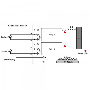
Here is the circuit diagram of receiver. You can connect motor 1 to OUT 1 terminal and motor 2 to OUT 2 terminal. After supply power to receiver, you press the button of transmitter, the motors will rotation or stop by wireless remote control.

circuit diagram

The wireless remote control equipment is L control mode. You operate as the processes:


Press button C: Turn on motor 1, terminal OUT 1 (A&B) output DC power.

Turn off motor 2, terminal OUT 2 no output.

Press button B: Turn on motor 2, terminal OUT 2 (A&B) output DC power.

Turn off motor 1, terminal OUT 1 no output.

Press button A: Turn off both motor 1 and motor 2, terminal OUT 1 and OUT2 no output.


Finally you can enter into the website and search the wireless remote control equipment as following:

Model: 0020422 (S2XL-DC12 & C-3)


Website:

http://www.carymart.com/radio-frequency-latching-remote-controller-receiver-2-function-dc-6v-9v-12v-24v-output-p-1408.html


http://www.ourautomation.com/radio-frequency-latching-remote-controller-receiver-2-function-dc-6v-9v-12v-24v-output-p-1408.html

RF Wireless Siren for Burglar Alarm Unit

A security system is a system designed to detect intrusion into a building or area. Some alarm systems serve a single purpose of burglary protection. We’d like to recommend this kind of burglar alarm Siren and transmitter/ receiver(S-02-B), which include a siren with red strobe light, wireless receiver module and wireless transmitter module, as a set of alerting device to work with your alarm system. It is wireless for easy installation. This siren is compatible with any burglar alarms. When it works, it generates sound with red strobe light. Alerting siren serve purpose of warning occupants of intrusion and potentially scaring off burglars and alert people.

004002

Operation:

Wireless siren is made by three parts: the transmitter, the siren and the receiver with the power adaptor. See following connection chart. Plug the transmitter to siren socket of the main unit, and plug the siren to the receiver, then plug the power adaptor of the receiver to AC110~240V. When the main unit triggers the alarm, the light of transmitter will shine, and it will send a wireless signal to the receiver of siren. The receiver gets the signal and output DC 12V power to the siren. Then the siren starts up.

003

If your alarm system works at 315 MHz, you should choose wireless siren with 433 MHz; if your alarm system works at 433 MHz, you should choose wireless siren with 315 MHz

Wireless remote control set with 6 relays

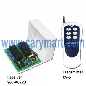
We recommend the wireless remote control facility here. It is model: S6C-AC220 & CV-6. The receiver (S6C-AC220) is 6 CH and supply power is AC 100~240V. The transmitter (CV-6) remote control distance is 500m/1500ft theoretically. The wireless facility can remote control lights, motors, fans, electrically operated doors/locks/windows/blinds/cars or other appliances with AC110~240V or DC0~28V. So you can connect 6 appliances to receiver and use the wireless transmitter to remote control appliances on/off.

receiver & transmitter

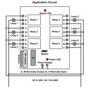
Here is the circuit diagram of receiver. You can connect 6 lamps to B terminal in the receiver. Then supply power to receiver by connecting live wire to “L” terminal and neutral wire to “N” terminal. When you press the button of transmitter, the lamps will turn on/off by wireless remote control.

circuit diagram

The wireless remote control facility has 6 control modes: toggle, momentary, latched, momentary+toggle, momentary+latched. We introduce toggle mode here. Of course you can also operate according to other control modes.

Operation as the toggle mode processes:

Press button 1: Turn on lamp 1 (connect B and C, disconnect A and B)

Press button 1 again: Turn off lamp 1 (disconnect B and C, connect A and B)


Press button 2: Turn on lamp 2 (connect B and C, disconnect A and B)

Press button 2 again: Turn off lamp 2 (disconnect B and C, connect A and B)


Press button 3: Turn on lamp 3 (connect B and C, disconnect A and B)

Press button 3 again: Turn off lamp 3 (disconnect B and C, connect A and B)


Press button 4: Turn on lamp 4 (connect B and C, disconnect A and B)

Press button 4 again: Turn off lamp 4 (disconnect B and C, connect A and B)


Press button 5: Turn on lamp 5 (connect B and C, disconnect A and B)

Press button 5 again: Turn off lamp 5 (disconnect B and C, connect A and B)


Press button 6: Turn on lamp 6 (connect B and C, disconnect A and B)

Press button 6 again: Turn off lamp 6 (disconnect B and C, connect A and B)


Finally if you want to know more something about the wireless remote control facility, you   can also enter into the website and search the product as following:

Model: 0020452 (S6C-AC220 & CV-6)


Website:

http://www.carymart.com/6-channel-500m-ac-220v-rf-remote-control-set-transmitter-receiver-p-1450.html


RF website:

http://www.rfcontrolsystem.com/index.php?main_page=product_info&cPath=361_352&products_id=1275


Remote Control System with Status Restore Function

We recommend this DC power no/nc contact memory function RC system (S1MU-DC06/09/12/24 & C-2). This remote control switch operates in 4 kinds of voltages, including 6V, 9V, 12V and 24V. It can remote control lights, motors, fans, electrically operated doors/locks/windows/blinds/cars or other appliances actuated by voltage ac 110~240V or DC 0~28V. Its transmission distance is 100m. There are 4 working modes in it. So you can switch working mode by connect and disconnect jumper. With function of memory, if the power is cut off, the relay will return automatically to the previous status after the power is restored.

memory remote controller

We’d like to show the wiring and controlling of ac, dc lamps.

The contact of relay of each receiver is normally open/ closed. So you need to wire ac lamp or dc lamp to normally open contact B&C and supply AC 220V power or dc power to lamp.

wiring diagram

Operation:

Setting control mode Toggle: Only connect Jumper-2.

Control mode Toggle: Press -> On; Press again -> Off.


Setting control mode Momentary: Only connect Jumper-1.

Control mode Momentary: Press and hold -> On; Release -> Off.


Setting control mode Latched: Do not connect Jumper-1 and Jumper-2.

Control mode Latched: Press -> On, another relay Off; Press another button -> Off.