4 Channel DC Output Remote Controller for Garden Lamps and Pond Pump

Overview:

I’m interested in buying transmitters and receivers 12 volts for three garden lights and one pond pump, but could you please advise me on which accessories and channels I would need for this?

garden light 1  pond pump

Solution:

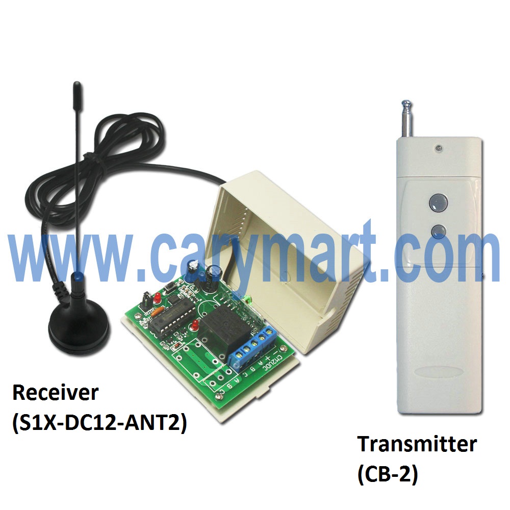
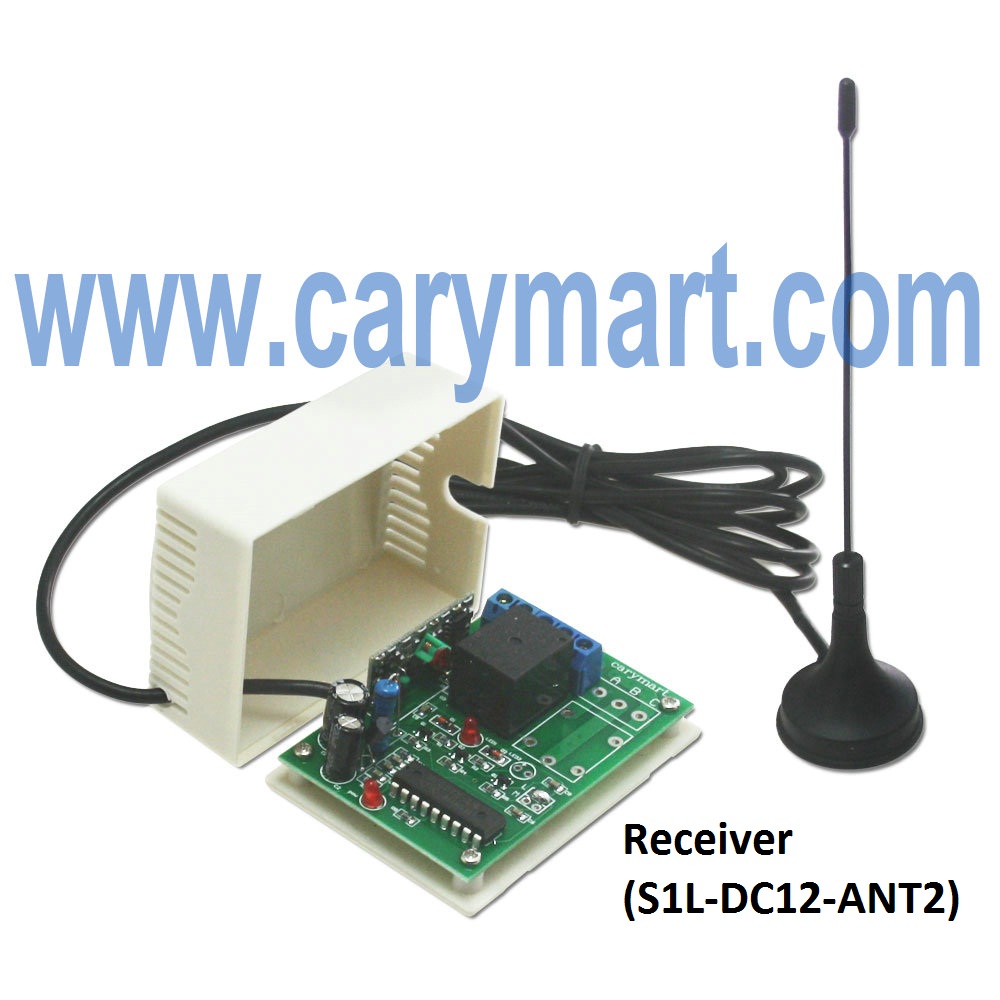
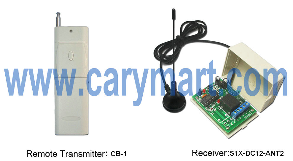
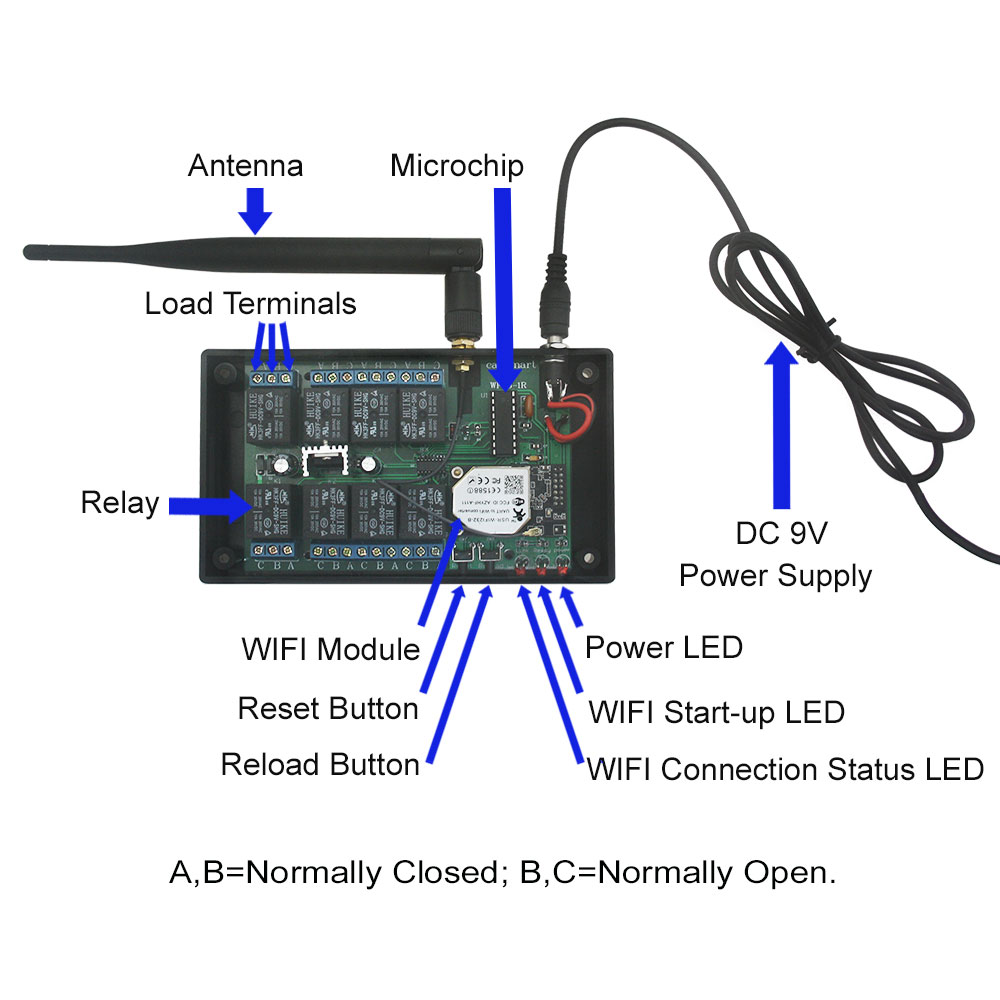
We recommend 4 Channel DC Output Long Range Kit (S4X-DC12-ANT2 & CB-4L). 4 channels can output 12V power, so garden lights and pond pump can be wired to terminals of relays respectively. It is 10amps of each channel. The transmitting distance is up to 2000m (6000FT) in open air with external mount antenna. It is very appropriate for outside pond pump and garden lights.

1_01

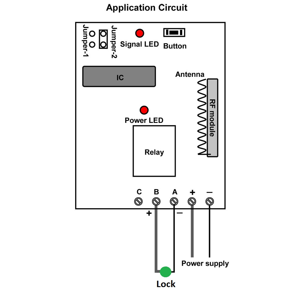
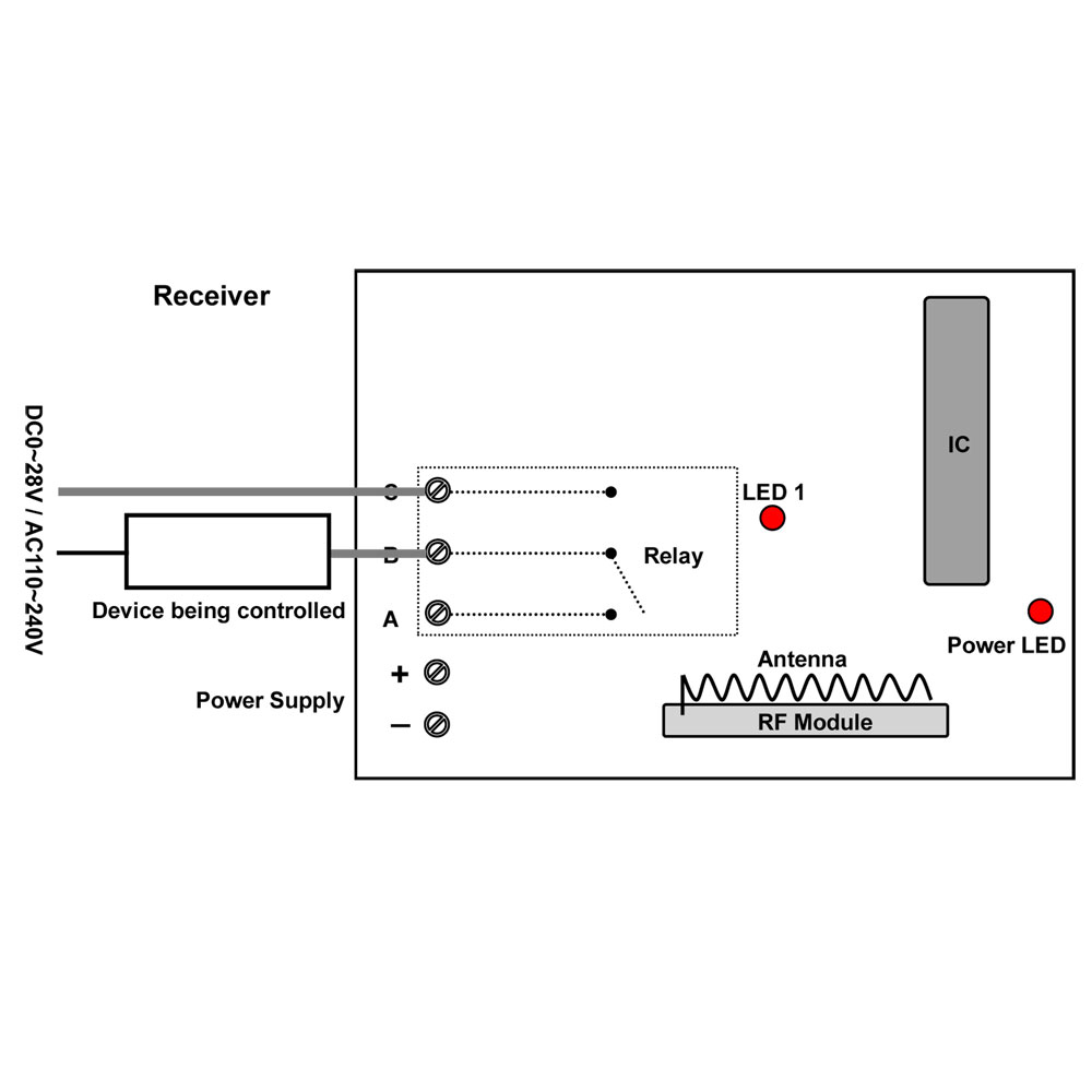
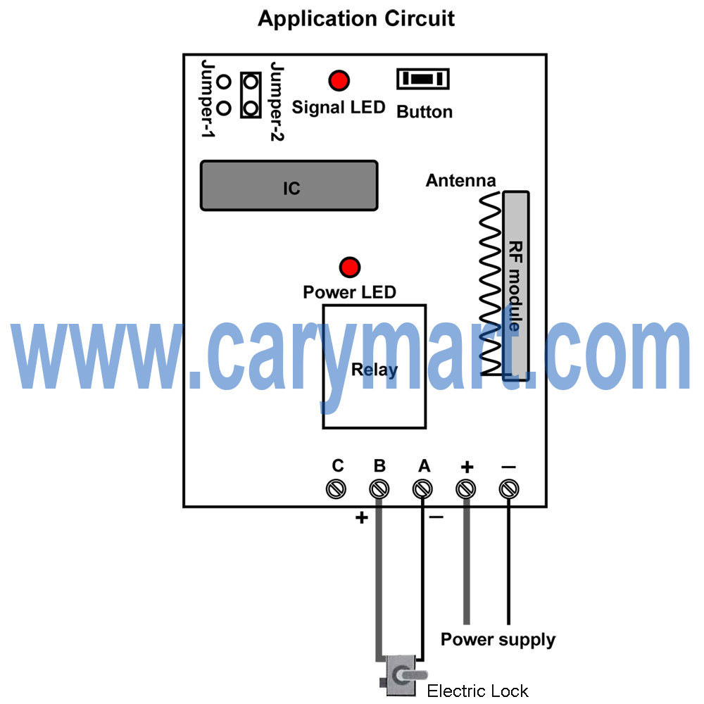
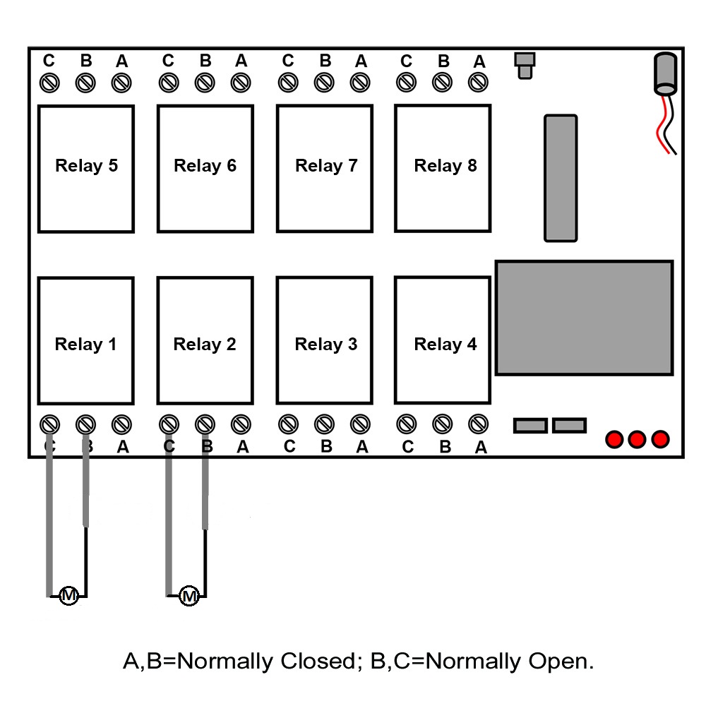
Wire three garden lights and pond pump to four relay terminals one by one. Supply 12V power, switch on power. Receiver, garden lights and pond pump turn on immediately.

circuit-diagram

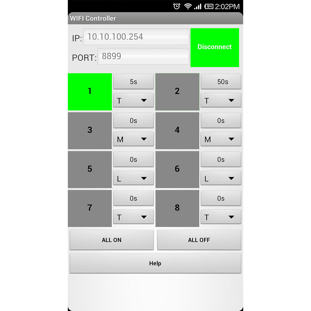
Setting control mode Toggle: (Only connect Jumper-2).

Press button A, turn on light 1; Press button A again, turn off light 1.

Press button B, turn on light 2; Press button B again, turn off light 2.

Press button C, turn on light 3; Press button B again, turn off light 3.

Press button D, turn on pond pump; Press button D again, turn off pond pump.

Remote control lock of door on/off by wireless control system

Question from customer:

We are a manufacturer of refrigerated ice storage reach in cases. We are considering an application to remotely unlock the doors using an electric strike. The application would most likely use a remote with a range of less than 150 feet typically. I am interested in getting some information about components that you might have that would work for this application.

Answer:

You can consider use the wireless remote control system according to your requirement. It is model: S1X-DC12-ANT2 & CB-2.The receiver (S1X-DC12-ANT2) is 1 channel and output power is DC6V/9V/12V/24V. The transmitter (CB-2) is suitable for long range remote control and distance is 1000m/3000ft theoretically. After you mount receiver to lock, you can use wireless transmitter to remote control unlock the door.

1_01

Here is the circuit diagram of receiver. You can connect lock to “A & B” output terminal of receiver. Then supply power to receiver. You press the button of transmitter and the lock will on or off by wireless remote control.

 1_06

There are three control modes for the wireless remote control system: toggle, momentary, latched. You can set any one of three modes as the operation:


When you only connect jumper-2, it is toggle mode.

Press big button: Turn on the lock, terminal A&B output DC power.
Press big button again: Turn off the lock, terminal A&B no output.


When you only connect jumper-1, it is momentary mode.

Press and hold big button: Turn on the lock, terminal A&B output DC power.
Release big button: Turn off the lock, terminal A&B no output.


When you don’t connect jumper-1 and jumper-2, it is latched mode.

Press big button: Turn on the lock, terminal A&B output DC power.
Press small button: Turn off the lock, terminal A&B no output.


By the way, you can also enter into our website and search the wireless remote control system as following:

Model: 0020491 (S1X-DC12-ANT2 & CB-2)

Website:

http://www.carymart.com/1channel-2000m-wireless-control-system-input-output-12v-p-1501.html

RF

http://www.rfcontrolsystem.com/index.php?main_page=product_info&cPath=173_422&products_id=1324

1 channel DC wireless kit of remote control runway lights

Question from customer:

I am looking for a remote and multiple receivers for a small private airport. We have a controller box switch that activates when you key the microphone 7 times on a specific frequency.  I would like to plug a dc power adapter into this unit and wire into one of your remotes. The runway lights are all solar dc leds. I will need 12 receivers total to start out. My question is:  Can one remote, controlled by external wires, send a signal out to multiple receivers at the same time?  In other words, if the remote detects dc input and sends out an ON signal, can several receivers receive the ON signal at the same time?

This is the remote I’m looking at.

http://www.rfcontrolsystem.com/index.php?main_page=product_info&products_id=1360

If I want to add additional receivers, what product number do I need or which receiver do I need to buy for this application?

9c678b65306443235f54ad3ad92c0250

Answer:

We advise you to use the receiver according to your requirement. It is model: S1L-DC12-ANT2 & CB-2V. The receiver (S1L-DC12-ANT2) is 1 channel and working voltage range of relay is AC110~240V or DC0~28V. The transmitter (CB-2V) can connect two wires to other device and remote control distance is 1000m/3000ft theoretically. You can mount receivers to each runway light and connect the transmitter to your controller box by two wires. Once the control box triggers the transmitter, it will launch wireless RF signal “ON” receivers at the same time. Then the runway lights will turn on by wireless remote control.

1_021_09


Here is the circuit diagram of receiver. You can connect runway light to “ B & C” terminal of receiver. Then supply power to receiver. When the transmitter is triggered by your controller box, it launch signal “ON” to receiver and relay to close. The runway lights will automatically turn on by wireless remote control; when the controller box is cut, the transmitter launch signal “OFF” to receiver and relay to open. The runway lights will automatically turn off by wireless remote control.

1_06

Finally you can also enter into the website and search the wireless remote control kit as following:


Model: S1L-DC12-ANT2 & CB-2V


Website:

S1L-DC12-ANT2

http://www.carymart.com/normally-open-rf-remote-control-kit-apply-for-device-control-ano

ther-device-1ch-dc-2000m-p-1548.html


CB-2V

http://www.rfcontrolsystem.com/index.php?main_page=product_info&products_id=1360


Remote Controller Unlocks Electric Lock

Overview:

We manage a refrigerated ice storage. We are considering an application to remotely unlock the doors using an electric strike. The application would most likely use a remote with a range of less than 150 feet typically. I am interested in getting some information about components that you might have that would work for this application.

Solution:

We recommend 1 channel 2000m dc power output receiver (S1X-DC12-ANT2) and 1-button transmitter (CB-1). Input power and output power of receiver are same as dc 12v. So it is easy for wiring. Maximum working current is 10amp. Working distance of remote and receiver set is about 2000m (6000ft) in open field. The RF signal can pass through walls, doors and other obstacles.

 remote-control-module-copy                      

Wire electric door lock and dc 12V power supply to the receiver accroding to the wiring diagram. Receiver is dc power output contact so you can connect door lock to A&B terminals. Electric door lock will get power from powered receiver.

1_06

Setting control mode Momentary: Only connect Jumper-1.

Press and hold big button: Turn on the relay, terminal A&B output DC power.

Release big button: Turn off the relay, terminal A&B no output.

When the door is locked, you can press and hold big button of the transmitter, the door will unlock.

electric-lock remote controlling set

8 channels relay output wireless WIFI controller of remote control motor by android device

Question from customer:

I am looking for a WIFI controller to operate 2 motors (Forward and Reverse) I would like this controller to be operated by a android or IOS device.

Answer:

We introduce the wireless WIFI controller to you according your requirement. It is model: WF-8-1R. The WIFI controller is 8 channels relay output power and working voltage range is AC110~240V or DC0~28V. Its remote control distance is 150m theoretically. If you want to remote control motor, you need to connect motor to the output terminal of WIFI controller. After you install the WIFI controller software to your mobile phone, you can remote control motor rotates in forward and reverse direction by using your mobile phone. Besides, the WIFI controller can control lights, fans, electric doors / windows, aircraft, remote cars, remote toys, rolling blinds, pumps, winches, or other electrical devices with voltage AC110~240V or DC0~28V.

1_03

Here is the circuit diagram of WIFI controller. You can connect two motors to “B & C” output terminal of WIFI controller. Then supply power to WIFI controller. And you can operate your mobile phone to remote control motors rotate in the positive and reversal direction.

1_08 1_05

There are four working modes for the WIFI controller: toggle, momentary, latched, and time delay. We have set the default toggle control mode as following operation:

Firstly, you need to connect wireless network to your mobile phone. Here is android software system. When click the ▼ icon of any channel in the mobile phone and choose T, it is toggle control mode. As the picture, click the icon of the relay 1 and the color of icon changes to green, it means relay 1 will be on, motor rotates. Click the icon again, the relay 1 will be off, motor stop rotating.

 1_16

Finally, you can know more something about the WIFI controller by enter into the website. You can search the product as following:

Model: 0022001 (WF-8-1R)

Website:

http://www.carymart.com/mobile-phone-smartphone-wifi-controller-for-android-or-ios-–-8-channel-relay-output-p-1579.html

RF

http://www.rfcontrolsystem.com/index.php?main_page=product_info&cPath=0&products_id=1389