2000m DC ON/OFF Switch Remote Control Motor

Question from Customer:

I seek a transmitter-receiver 12V to run a small motor away from 300~500 meters with operating on off.

Answer:

Our suggestion is this 1 channel 12V voltage output remote control gadget (S1X-DC12-ANT2 & CB-2). Single channel is for one device. 12V direct power output can supply power directly to the device which is controlled. User can turn on/off the receiver with transmitter (remote control) from any place within a reliable distance; the wireless RF signal can pass through walls, floors and doors. The receiver, which mounts long range magnetic antenna, pairs with long distance transmitter to reach to 2000m in the open field.

remote control unit&motor

There are 3 control modes. They are Toggle, momentary and latched.

Setting control mode Toggle: Only connect Jumper-2.

1) Press big button: Turn on the relay.

Press big button again: Turn off the relay.

2) Setting control mode Momentary: Only connect Jumper-1.

Press and hold big button: Turn on the relay.

Release big button: Turn off the relay.

3) Setting control mode Latched: Do not connect Jumper-1 and Jumper-2.

Press big button: Turn on the relay.

Press small button: Turn off the relay.

As regards controlling motor on and off, we suggest the latched mode. Latched mode is really favorable for long range controlling because big button on transmitter is for ON, small button is for OFF. If you want to turn on motor, you can press big more for many times to make sure that the motor is on. If you want to turn off motor, you can press small more for many times to make sure that the motor is off.

For the wiring, it is so simple. The following picture shows. Motor is connected to terminals A&B on the receiver. The receiver should be supplied 12V power. There is no need to supply power to motor because motor can get power from the receiver.

receiver

Turn on Hot Water Circulator and Make it off Automatically

Question from customer:

I want to use one device to turn on a hot-water circulator in my home for 15 minutes&then have it automatically turn off. I live in a 2 story wood home&the hot-water circulator is in the basement-maybe a distance of about 30 ft away through drywall&wood flooring. Will it work over this distance? Would I need to order a telescopic antenna?

hot-water-circulator 2

Answer:

We think this product may be suitable for you– 1 channel ac delayed remote unit (0020483 S1DA-AC220-ANT2+CB-2). This kind of remote unit is with time delay timer, which you can adjust time according to your requirement. With external extend magnetic antenna, working distance of transmitter and receiver will reach 2000m/6000ft (theoretically).So you don’t have to order telescopic antenna.

1_01

Wiring program is as follow:

We connect delayed remote unit to circulator pump. The receiver is relay output (normally open and normally closed). Power supply for the receiver and the water pump are different. That means it will not cause electromagnetic interference during water pump operation.

S1DA-AC and pump

Operation:

Press big button: Turn on relay (connect B and C, disconnect A and B). After delay time: Turn off relay by itself (disconnect B and C, connect A and B). Press small button: Turn off relay immediately, no need to wait for delay time.

Press buttons of “+” and “-” on the timer, adjust delay time from 0 second to 99 hours. “H” is Hour, “M” is Minute, and “S” is Second. As your requirement, you can set “M 1 5”, it means the delay time is 15 minutes. After working for 15 minutes, it will be off automatically. Then the circulator pump stops pumping.

Manual Switch on/off to Remote Control LED On the Receiver

Question from customer:

I want a remote controlling unit that the transmitter is to function as a switch to the receiver activated by supplying a 12V DC current to the transmitter (switch it on). The receiver then permits a 12V DC current to be supplied to a designated appliance. When the transmitter is shut off the receiver will shut down.

T R 12V DC #3

Answer:

Maybe this kind of controlling unit —12V power Input RF remote control system (S1XL-DC12-ANT2+CB-2V) is suitable for you. It is applied for device controlling another device. The characteristic of the transmitter CB-2V will be triggered by DC power 5~28V input. We add external extended antenna which makes transmitting distance up to 2000m.

1_01

According to the picture above, he wants the transmitter can be activated by manual switch and turn receiver on/off when the current in that circuit is on/off. First, the transmitter is supposed to be connected to power supply and that manual switch. Second, designated appliance should be connected to receiver.

S1XL-DC12circuit

We prepare a demonstration for this practical use.

CB-2V-and manual switch

We switch on the manual switch and the transmitter will send an “ON” signal to the receiver. The receiver receives the signal to instruct the light to turn on. We switch off the manual switch and the transmitter will send an “OFF” signal to the receiver. The receiver receives the signal to instruct the light to turn off.

S1X-DC+CB-2V-lamp on

Manual and Remote Switch Control Dock Light

Question from customer:

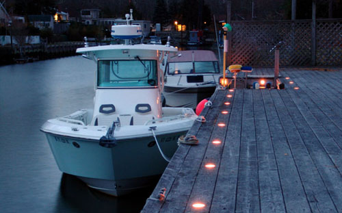
I have a dock light (120v) that I would like to be able turn it on/off with a regular switch on the wall and/or a remote from the boats. Do you have something that will do that?

dock light 2

Answer:

We recommend the model of controlling unit—wall switch and remote transmitter (HS-1+CP-1). This controlling unit contains a wall switch and remote transmitter.

001

As your requirement, a regular switch on the wall is our wall switch product, and it pairs with a remote transmitter which is portable for you to use from the boats. This unit controls lamps, fans or other appliances with voltage AC 100~250V. It is also suitable for Incandescent lamps, halogen lamps, fluorescent lamps and energy saving lamps. But it cannot work in LED lamps. By them, you can turn on/ off the lamp with remote control from any place within a reliable distance, the wireless signal can pass through walls, floors and doors.

Let’s see about the wiring diagram and practical application procedure. At first, we should follow the wiring diagram to do some wiring. Taking apart the wall switch, then you can connect wires. Neutral wire is connected to AC lamp. Wire AC lamp to terminal “Out 1” of wall switch. Live wire is connected to terminal “In” of wall switch.

012

After fixing wall switch on the wall with screws, we can learn remote control to wall switch. Then we can finish all installation.

006

Usage of Wall Switch:

When starting to walk to your dock from your house or parking your boat at dock after your tour, walking along trestle bridge to your house, you can press button, turn on the lamp; Press button again, turn off the lamp.

Usage of remote control transmitter CP-1:

After your departure from dock by your boat or arrival at dock, you can press button, turn on the lamp; Press button again, turn off the lamp.

We believe that this unit can meet your demand.

Toggle/Momentary/Latched/Mixed-mode Remote Controlling Operation

Through learning or deleting code from transmitter to receiver, we can shift working mode easily. Different mode is applied for different controlling. Toggle mode is used for controlling lamp, doors, locks…Momentary is used for controlling rolling blind, shutter, rolling door…As regards the latched mode, it is motivated by relay group. Latched mode is available for long distance controlling (no line of sight, lots of trees or other obstacles in-between). And there is mixed mode of toggle+momentary. A relay group is toggle mode, the other relay group is momentary mode.

003

Here, we’d like to introduce the procedure of 4 working modes’ practical operations (4 Channel 12V multi-mode remote control).

Toggle mode: Connect jumper to CN2, set toggle control mode.

S4C-DC12&C-4 -T mode

Press any buttons to control corresponding lamp on and off.

Press button 1, turn on lamp 1.

S4C-DC12&C-4-T mode button 1 on

Press button 1 again, turn off lamp 1.

S4C-DC12&C-4 -T mode button 1 off

Momentary mode: Connect jumper to CN1, set momentary control mode.

S4C-DC12&C-4 -M mode

Press any buttons to control corresponding lamps on and off. Such as: Press and hold button 2, turn on lamp 2; release button 2, turn off lamp 2.

Press and hold button 3, turn on lamp 3; release button 3, turn off lamp 3.

S4C-DC12&C-4 -M mode lamp on

Latched mode: No jumper connect, set latched control mode.

S4C-DC12&C-4 -L mode

Press any buttons to control corresponding lamps on and off. Such as: Press button 1, turn on lamp 1. Other lamps are off.

Press button 2, turn on lamp 2. Other lamps are off…

S4C-DC12&C-4 -L mode button 3 on

Momentary+Latched mode: Connect jumper to CN1 and CN2, set momentary and latched mode.

S4C-DC12&C-4-M+T mode

Press corresponding buttons to corresponding operation

Momentary Mode:(Channel 1~2)

S4C-DC12&C-4 -M+T mode button 1 on

Toggle Mode:(Channel 3~4)

S4C-DC12&C-4 -M+T mode button 3 on

Video: